MAKE CONNECTIONS
The OpenComms EM must be installed indoors where electrical service is available. The unit should be placed where it can be easily accessed for making connections. It may be placed on a flat surface or mounted on a wall (see the user manual for mounting instructions). Consider the length of the sensor and other cables and the distance to the monitored area when deciding where to place the unit.
Refer to Figure 1 when making the connections in Steps 1 - 5 below to the ports on the back of the OpenComms EM. The port placement and port labels differ for each model.
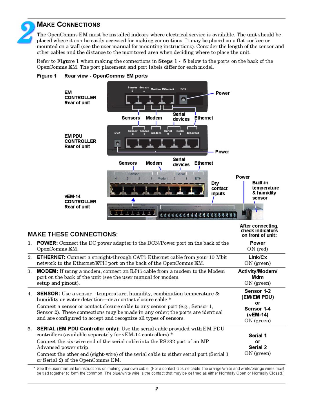
Figure 1 Rear view - OpenComms EM ports
|
| Sensor Sensor | Modem Ethernet DCN |
|
|
| ||||||||
EM | 2 |
| 1 |
|
|
|
|
|
|
|
|
| Power | |
|
|
|
|
|
|
|
|
|
|
|
|
| ||
CONTROLLER |
|
|
|
|
|
|
|
|
|
|
|
|
|
|
Rear of unit |
|
|
|
|
|
|
|
|
|
|
|
|
|
|
|
|
|
|
|
|
|
|
|
|
| ||||
|
|
|
|
|
|
| Serial |
|
|
| ||||
| Sensors | Modem | Ethernet | |||||||||||
| devices | |||||||||||||
EM PDU CONTROLLER Rear of unit
DCN | Sensor | Sensor | Modem | Serial | Serial | Ethernet |
| 2 | 1 |
| 2 | 1 |
|
Power |
Serial
Sensors Modem devices Ethernet
Power
Dry contact inputs
& humidity |
sensor |
CONTROLLER
Rear of unit
| After connecting, | |
MAKE THESE CONNECTIONS: | check indicators | |
on front of unit: | ||
1. POWER: Connect the DC power adapter to the DCN/Power port on the back of the | Power | |
OpenComms EM. | ON (red) | |
2. ETHERNET: Connect a | Link/Cx | |
network to the Ethernet/ETH port on the back of the OpenComms EM. | ON (green) | |
3. MODEM: If using a modem, connect an RJ45 cable from a modem to the Modem | Activity/Modem/ | |
port on the back of the unit (see the user manual for modem | Mdm | |
setup and pinout). | ON (green) | |
4. SENSOR: Use a | Sensor | |
humidity or water | (EM/EM PDU) | |
Connect a sensor or contact closure cable to any sensor port (e.g., Sensor 1, | or | |
Sensor | ||
Sensor 2). These connections may be made in any order; the ports are identical | ||
| ||
and are configured to accept and recognize all types of sensors. | ||
ON (green) | ||
| ||
|
| |
5. SERIAL (EM PDU Controller only): Use the serial cable provided with EM PDU |
| |
controllers (available separately for | Serial 1 | |
Connect the | or | |
Advanced power strip. | Serial 2 | |
Connect the other end | ON (green) | |
or Serial 2) of the OpenComms EM. |
|
*See the user manual for instructions on making your own cable. (For a contact closure cable, the orange/white and white/orange wires must be tied together to form the common. The blue/white wire is the contact that may be defined as either Normally Open or Normally Closed.)
2