SECTION 4 ADJUSTMENTS
Time Delay Adjustment
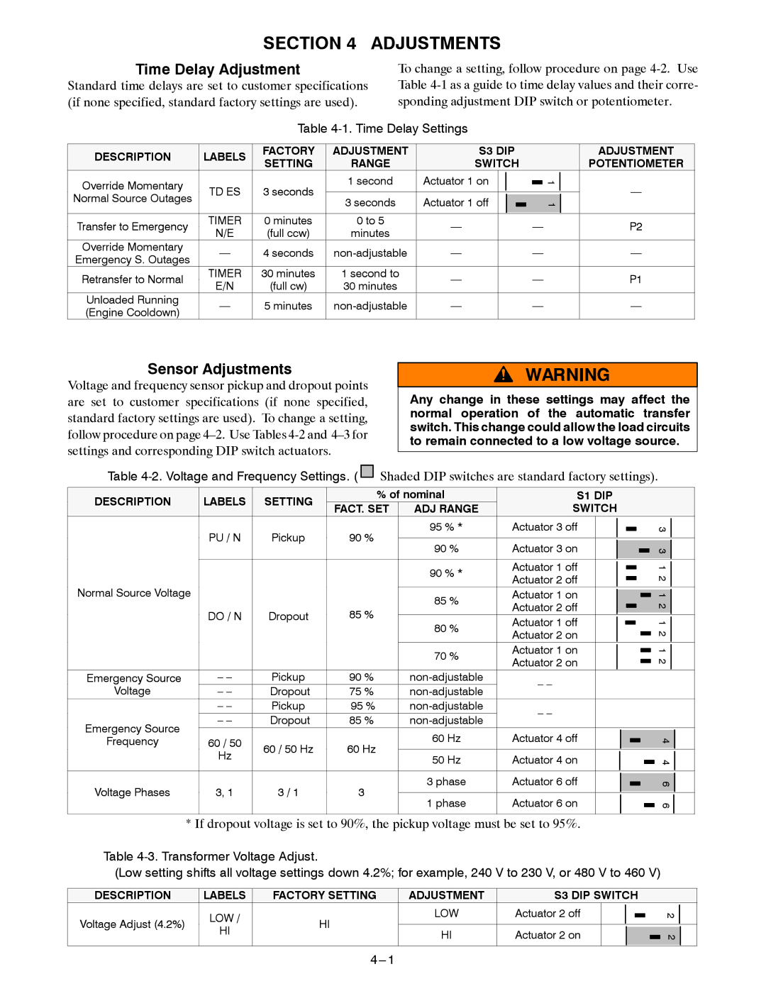
Standard time delays are set to customer specifications (if none specified, standard factory settings are used).
To change a setting, follow procedure on page
|
| Table | ||||||
|
|
|
|
|
|
|
| |
DESCRIPTION | LABELS | FACTORY | ADJUSTMENT | S3 DIP | ||||
SETTING | RANGE | SWITCH | ||||||
|
| |||||||
Override Momentary | TD ES | 3 seconds | 1 second | Actuator 1 on |
|
|
| |
Normal Source Outages | 3 seconds | Actuator 1 off |
|
|
| |||
|
|
|
|
| ||||
|
|
|
|
|
| |||
Transfer to Emergency | TIMER | 0 minutes | 0 to 5 | — |
|
|
| |
N/E | (full ccw) | minutes |
| |||||
|
|
|
|
| ||||
Override Momentary | — | 4 seconds | — |
|
|
| ||
Emergency S. Outages |
| |||||||
|
|
|
|
|
|
| ||
Retransfer to Normal | TIMER | 30 minutes | 1 second to | — |
|
|
| |
E/N | (full cw) | 30 minutes |
| |||||
|
|
|
|
| ||||
Unloaded Running | — | 5 minutes | — |
|
|
| ||
(Engine Cooldown) |
| |||||||
|
|
|
|
|
|
| ||
|
|
|
| ADJUSTMENT |
|
|
|
| POTENTIOMETER |
|
| 1 |
| — |
|
|
| ||
|
|
| ||
|
| 1 |
| |
|
|
| ||
|
|
|
| |
— |
|
| P2 | |
|
| |||
— |
|
| — | |
— |
|
| P1 | |
— |
|
| — | |
|
|
|
|
|
Sensor Adjustments
Voltage and frequency sensor pickup and dropout points are set to customer specifications (if none specified, standard factory settings are used). To change a setting, follow procedure on page
Any change in these settings may affect the normal operation of the automatic transfer switch. This change could allow the load circuits to remain connected to a low voltage source.
Table ![]()
![]() Shaded DIP switches are standard factory settings).
Shaded DIP switches are standard factory settings).
DESCRIPTION | LABELS | SETTING | % of nominal | S1 DIP | ||||
FACT. SET | ADJ RANGE | SWITCH | ||||||
|
|
| ||||||
| PU / N | Pickup | 90 % | 95 % * | Actuator 3 off |
|
| |
| 90 % | Actuator 3 on |
|
| ||||
|
|
|
|
|
| |||
|
|
|
| 90 % * | Actuator 1 off |
|
| |
|
|
|
|
| ||||
|
|
|
| Actuator 2 off |
|
| ||
|
|
|
|
|
|
| ||
Normal Source Voltage |
|
|
| 85 % | Actuator 1 on |
|
| |
|
|
|
| |||||
|
|
|
| Actuator 2 off |
|
| ||
| DO / N | Dropout | 85 % |
|
|
| ||
| 80 % | Actuator 1 off |
|
| ||||
|
|
| ||||||
|
|
|
|
|
| |||
|
|
|
| Actuator 2 on |
|
| ||
|
|
|
|
|
|
| ||
|
|
|
| 70 % | Actuator 1 on |
|
| |
|
|
|
|
| ||||
|
|
|
| Actuator 2 on |
|
| ||
|
|
|
|
|
|
| ||
Emergency Source | – – | Pickup | 90 % | – – |
|
| ||
Voltage | – – | Dropout | 75 % |
| ||||
|
|
| ||||||
| – – | Pickup | 95 % | – – |
|
| ||
Emergency Source | – – | Dropout | 85 % |
| ||||
|
|
| ||||||
|
|
| 60 Hz | Actuator 4 off |
|
| ||
Frequency | 60 / 50 | 60 / 50 Hz | 60 Hz |
| ||||
| Hz | 50 Hz | Actuator 4 on |
|
| |||
|
|
|
|
| ||||
|
|
|
|
| ||||
Voltage Phases | 3, 1 | 3 / 1 | 3 | 3 phase | Actuator 6 off |
| ||
1 phase | Actuator 6 on |
|
| |||||
|
|
|
|
| ||||
|
|
|
|
|
|
|
| |
3 3 1 2 1 2 1 2 1 2![]()
4 4 6 6![]()
* If dropout voltage is set to 90%, the pickup voltage must be set to 95%.
Table
(Low setting shifts all voltage settings down 4.2%; for example, 240 V to 230 V, or 480 V to 460 V)
DESCRIPTION | LABELS | FACTORY SETTING | ADJUSTMENT | S3 DIP SWITCH | |||
Voltage Adjust (4.2%) | LOW / | HI | LOW | Actuator 2 off |
|
|
|
|
| ||||||
HI | HI | Actuator 2 on |
|
|
| ||
|
|
|
|
| |||
|
|
|
|
| |||
|
|
|
|
|
|
|
|
2 2![]()