MODEL 1056

WIRING

POWER, OUTPUT, AND SENSOR CONNECTIONS

Power wiring

The following power wiring instructions apply to all configurations for Model 1056. The power terminal can be wired with 18 - 12 AWG wire sizes. Wiring must be rated for 75°C or higher. Ensure that power has been turned off to the power leads during this installation.

Three Power Supplies are offered for Model 1056:

a.115/230VAC Power Supply (-01 ordering code)

b.24VDC (20 – 30V) Power Supply (-02 ordering code)

c.84 – 265 VAC Switching Power Supply (-03 ordering code)

AC mains (115 or 230V) leads and 24VDC leads are wired to the Power Supply board which is mounted vertically on the left side of the main enclosure cavity. Each lead location is clearly marked on the Power Supply board. Wire the power leads to the Power Supply board using the lead markings on the board.

The grounding plate is connected to the earth terminal of power supply input connector TB1 on the -01 (115/230VAC) and -03 (84-265VAC) power supplies. The green colored screws on the grounding plate are intend- ed for connection to some sensors to minimize radio frequency interference. The green screws are not intended to be used for safety purposes.

For UL-approved configurations of Model 1056 (1056-XX-XX-XX-XX-UL) a clear plastic protective shield is installed that surrounds the power supply connections. To wire power leads to the power supply:

a.Route the power cable or individual power leads through an appropriate cable gland fittings or conduit and through the left front instrument enclosure opening for the -01 supply. The -02 and -03 power supplies may be wired through either the front left or rear left conduit entry holes.

b.Route the leads up through the bottom of the plastic shield surrounding the power supply board.

c.Open the door of the plastic shield to gain access to the wiring connections. The door is locked to the protective shield with plastic tabs.

d.Remove the mating connector (location TB1 on the PCB) for the power connections.

e.Wire the individual leads to the modular mating connector for power connections.

f.Insert the wired modular connector into the board-mounted mating connector (TB1) on the power supply board. The connector is keyed.

g.Close the door of the plastic shield and secure it using the plastic locking tabs.

h.Make sure to properly seal the power wires that exit the enclosure with the appropriate cable glands or pipe fittings to ensure a NEMA-compliant enclosure.

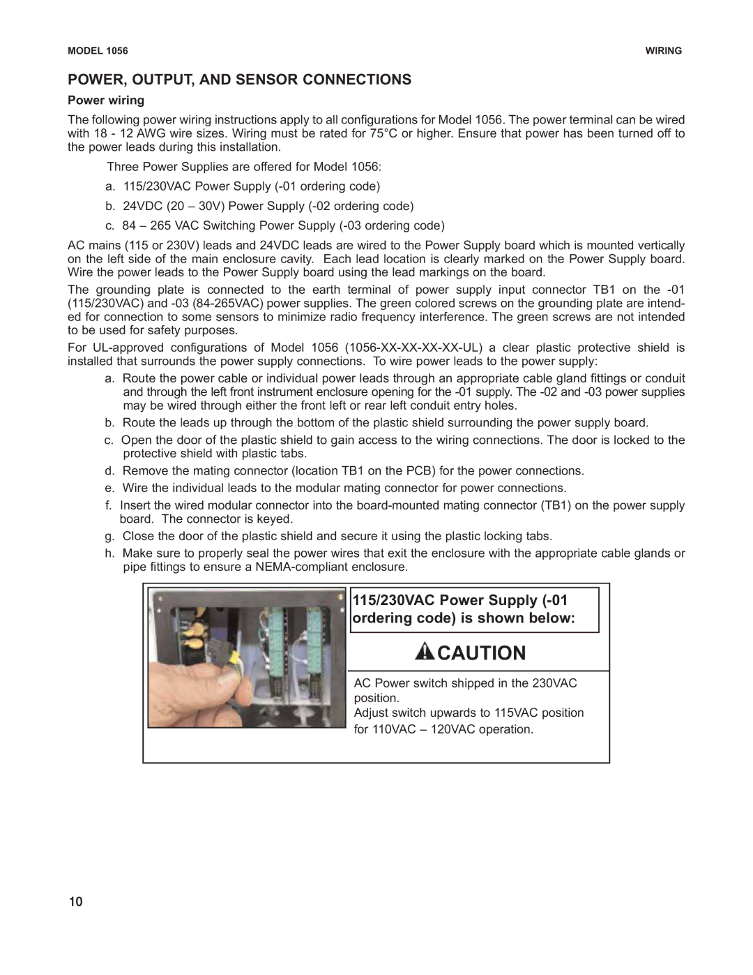
115/230VAC Power Supply (-01 ordering code) is shown below:

CAUTION

AC Power switch shipped in the 230VAC position.

Adjust switch upwards to 115VAC position

for 110VAC – 120VAC operation.

10

Page 10
Image 10
Emerson Process Management 1056 instruction sheet POWER, OUTPUT, and Sensor Connections, Power wiring

1056 specifications

Emerson Process Management's 1056 is a high-performance flue gas analyzer designed for industrial applications requiring precise measurement of combustion and emissions. This advanced analyzer is instrumental in optimizing combustion processes, ensuring regulatory compliance, and enhancing overall operational efficiency.

One of the key features of the Emerson 1056 is its multi-gas measurement capability. The device can simultaneously monitor multiple gases, such as oxygen, carbon dioxide, carbon monoxide, and nitric oxides. This comprehensive measurement range provides operators with critical insights necessary for managing combustion processes effectively.

The 1056 utilizes advanced infrared and electrochemical sensing technologies. The infrared sensors are particularly effective for measuring gases like CO₂ and CO, while electrochemical cells handle specific gases like O₂ and NOx. These technologies offer high accuracy and reliability across a wide temperature and pressure range, ensuring that the data collected is both timely and precise.

Another significant characteristic of the Emerson 1056 is its robust construction, which is designed to withstand harsh industrial environments. The analyzer features durable materials that resist corrosion and high temperatures, ensuring long-lasting performance. Additionally, the 1056 is equipped with a user-friendly interface that simplifies operation and data interaction. Its intuitive design allows users to access real-time data and easily configure settings, facilitating quick decision-making on the shop floor.

For communication and integration with existing systems, the 1056 supports various industry-standard protocols, such as HART, Modbus, and Ethernet/IP. This compatibility enables seamless integration into broader control and monitoring systems, allowing for enhanced data sharing and management.

Emerson has also placed a strong emphasis on serviceability with the 1056. The analyzer is designed for easy maintenance, with features that simplify calibration and routine checks. This reduces downtime and operational disruptions, ensuring continuous compliance with environmental regulations.

In conclusion, the Emerson Process Management 1056 stands out as a versatile and reliable flue gas analyzer, offering advanced measurement capabilities, robust construction, and seamless integration into industrial systems. Its combination of technology and user-centric design makes it an essential tool for industries striving for efficiency and compliance in their combustion processes.