Manuals
/
Emerson Process Management
/
Computer Equipment
/
Power Supply
Emerson Process Management
GFC, MICRO
manual
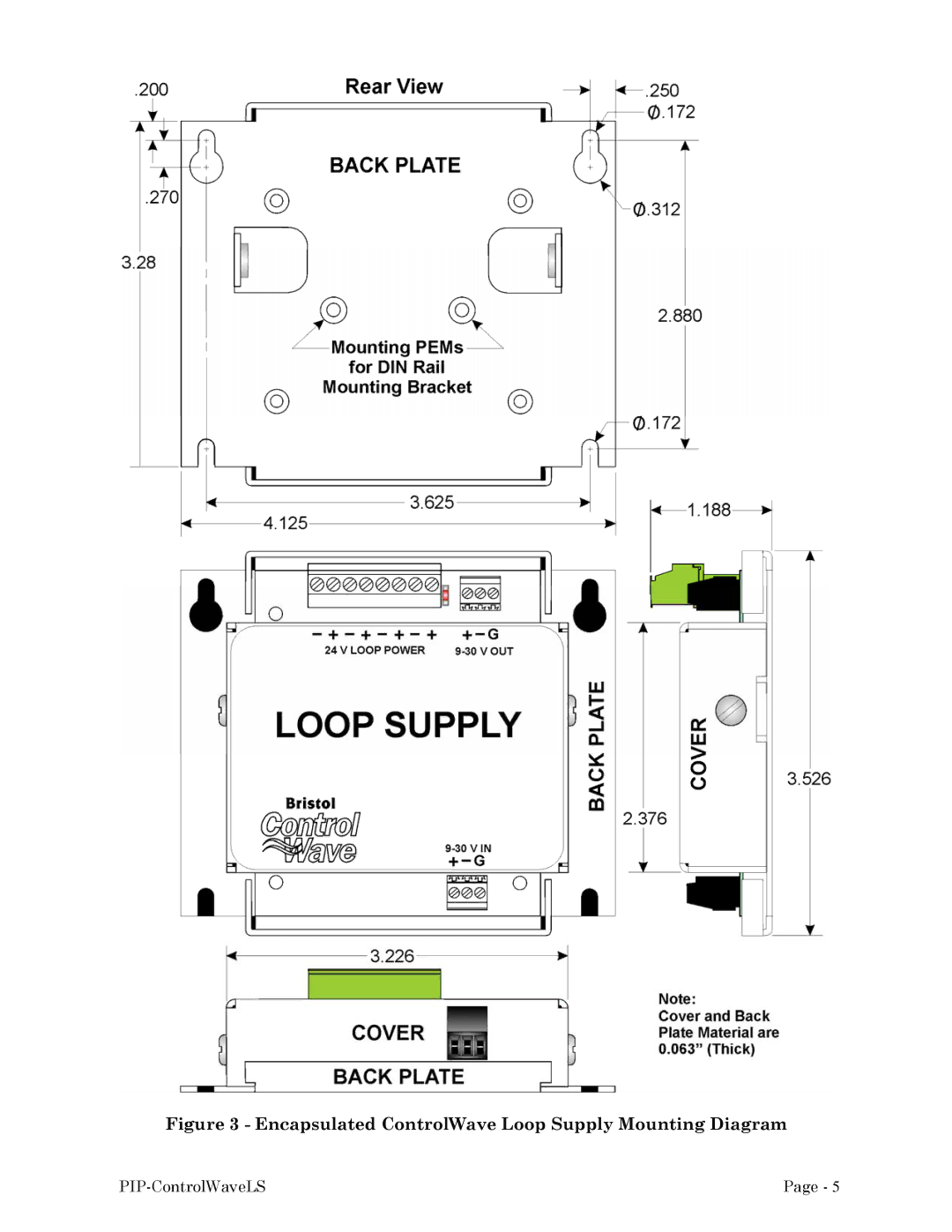
Encapsulated ControlWave Loop Supply Mounting Diagram
Models:
GFC
MICRO
1
14
23
23
Download
23 pages
4.07 Kb
11
12
13
14
15
16
17
18
Specifications
Install
Loop Supply Wiring
Warranty
Dimension
Configuration Jumper JP1
Connectors
= Power IN+
Page 14
Image 14
Figure 3 - Encapsulated ControlWave Loop Supply Mounting Diagram
PIP-ControlWaveLS
Page -
5
Page 13
Page 15
Page 14
Image 14
Page 13
Page 15
Contents
Product Installation Guide
IMPORTANT! Read Instructions Before Starting
Warranty
Phone
Mail
Bristol Inc
Bristol Inc. Repair Authorization Form off-line completion
Training
Few Words About Bristol Inc
860 860 945-2213 FAX
Visit our Site on the World Wide Web Training Courses
PIP-ControlWaveLS
Terminal Blocks
General Description
Loop Supply Component Identification
TB1 TB3
Power LED
Regulated 24V Supply Distribution Connector TB2
Configuration Jumper JP1
Fuse F1
Loop Supply Installation
Loop Supply Mounting
Encapsulated ControlWave Loop Supply Mounting Diagram
Power Input and Pass-through Wiring Considerations
Loop Supply Wiring
Field I/O Wiring Considerations
ControlWave Micro & EFM Loop Supply to I/O Module Wiring
= GND
= Power IN+
Operating Specifications
Environmental Specifications
Diminsions
Connectors
Part Numbers
Loop Supply Dimensions Drawing
ControlWave Loop Power Supply
Top
Page
Image
Contents