Induction Heater C Library User Manual Version 1.2
3. System Introduce
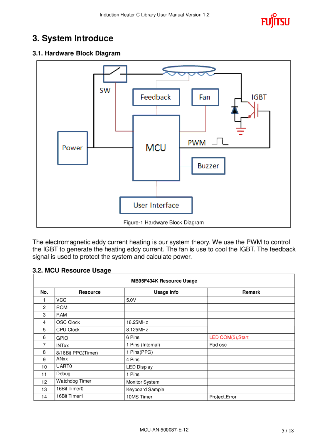
3.1. Hardware Block Diagram
Figure-1 Hardware Block Diagram
The electromagnetic eddy current heating is our system theory. We use the PWM to control the IGBT to generate the heating eddy current. The fan is use to cool the IGBT. The feedback signal is used to protect the system and calculate power.
3.2. MCU Resource Usage
MB95F434K Resource Usage
No. | Resource |
| Usage Info | Remark |
|
|
|
| |
1 | VCC | 5.0V |
| |
|
|
|
|
|
2 | ROM |
|
|
|
|
|
|
|
|
3 | RAM |
|
|
|
|
|
|
| |
4 | OSC Clock | 16.25MHz |
| |
|
|
|
| |
5 | CPU Clock | 8.125MHz |
| |
|
|
|
|
|
6 | GPIO | 6 | Pins | LED COM(5),Start |
7 | INTxx | 1 | Pins (Internal) | Pad osc |
8 | 8/16Bit PPG(Timer) | 1 | Pins(PPG) |
|
9 | ANxx | 4 | Pins |
|
|
|
|
| |
10 | UART0 | LED Display |
| |
|
|
|
|
|
11 | Debug | 1 | Pins |
|
|
|
|
| |
12 | Watchdog Timer | Monitor System |
| |
|
|
|
| |
13 | 16Bit Timer0 | Keyboard Sample |
| |
|
|
|
| |
14 | 16Bit Timer1 | 10MS Timer | Protect,Error | |
|
|
|
|
|
5 / 18 |