Induction Heater C Library User Manual Version 1.2
4.3. Main Board
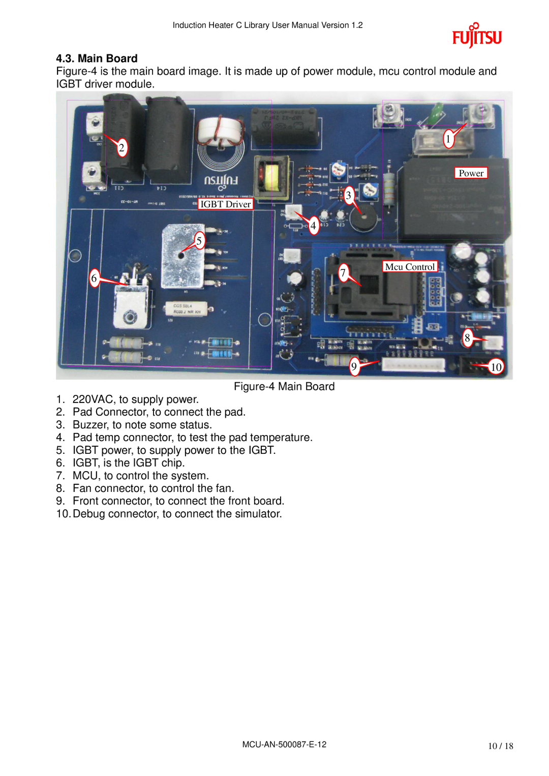
Figure-4 is the main board image. It is made up of power module, mcu control module and IGBT driver module.
| 2 | 1 |
|
| |
|
| Power |
| IGBT Driver | 3 |
|
| |
| 4 |
|
| 5 |
|
6 | 7 | Mcu Control |
| ||
|
|
8
9 | 10 |
Figure-4 Main Board
1.220VAC, to supply power.
2.Pad Connector, to connect the pad.
3.Buzzer, to note some status.
4.Pad temp connector, to test the pad temperature.
5.IGBT power, to supply power to the IGBT.
6.IGBT, is the IGBT chip.
7.MCU, to control the system.
8.Fan connector, to control the fan.
9.Front connector, to connect the front board.
10.Debug connector, to connect the simulator.
10 / 18 |
