Testing Defrost Operation using test pins
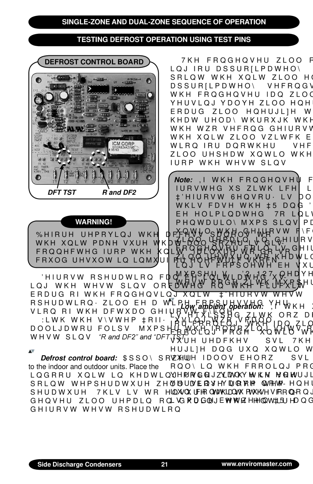
Defrost Control Board
DFT TST | R and DF2 |
Warning!
Before removing the access panels to the unit make sure that all power is dis- connected from the unit. Failure to do so could result in injurf or electric shock.
Defrost operation can be initiated us- ing the test pins located on the circuit board of the condensing unit. “Defrost test operation” will be a time compressed ver- sion of the actual defrost cycle.
With the system “off”, using two small alligator clips, jumper the following sets of test pins. “R and DF2” and “DFT TST”.
Defrost control board: Apply power to the indoor and outdoor units. Place the indoor unit in heating mode with the set point temperature well above room tem- perature. This is to ensure that the con- denser will remain on during the entire defrost test operation.
The condenser will operate in heat- ing for approximately 20 seconds. At that point the unit will enter defrost mode for approximately 2 seconds. During this time the condenser fan will switch off, the re- versing valve will energize and the defrost board will energize the indoor electric heat relay through the “W” terminal. After the two second defrost cycle is complete, the unit will switch back to heating opera- tion for another 20 seconds. This process will repeat until the jumpers are removed from the test pins.
Note: If the condenser coil is heavily frosted up with ice, it is likely that the “Defrost Sensor” is already closed. In this case the “R and DFT” jumper can be eliminated. To initiate defrost, mo- mentarily jump pins marked “DFT TST” until the defrost cycle begins. The unit will remain in defrost mode until the condenser coil is defrosted and then it will return to heating mode. When test- ing is complete be sure to remove the jumper(s). DO NOT leave the unit in test mode with jumper(s) in place.
Low ambient operation: If the unit is equipped with low ambient fan control for cooling, the fan will remain off (while in cooling mode) until the condenser pres- sure reaches 210psi. The fan will then en- ergize and run until the condenser pres- sure falls below 150psi. This will happen only in the cooling mode (or when the re- versing valve is energized). In heating (re- versing valve not energized), the fan will run continuous so long as the connection is made between “R” and “Y”.
Side Discharge Condensers | 21 | www.enviromaster.com |