MPS-1 specifications
The Emotiva MPS-1 is a powerful and versatile multi-channel amplifier designed to enhance audio performance in both home theaters and high-fidelity music systems. Known for its robust construction and high-quality sound output, the MPS-1 stands out as an ideal choice for audiophiles and home theater enthusiasts alike.One of the defining features of the MPS-1 is its impressive power output. The amplifier delivers 200 watts per channel into 8 ohms and 300 watts into 4 ohms, providing ample headroom to drive even the most demanding speakers. This high power output ensures that users can enjoy dynamic sound without compromising on clarity or detail, making it suitable for both movies and music.
The MPS-1 utilizes advanced Class AB amplification technology, combining the efficiency of Class A with the thermal performance of Class B. This design minimizes distortion and maximizes linearity, ensuring that the sound remains clean and accurate across a wide frequency range. The amplifier also features a high-current output stage, allowing it to handle sudden peaks in audio without clipping, an essential quality for impactful sound reproduction.
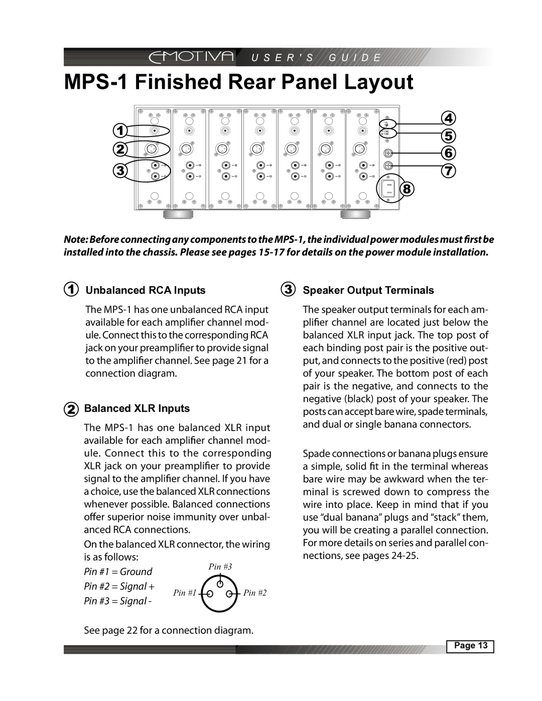
Another significant aspect of the MPS-1 is its comprehensive connectivity options. It is equipped with both balanced XLR and unbalanced RCA inputs, providing flexibility for integration into various audio setups. The amplifier can also be configured to operate in a bridged mode, effectively doubling the output power to drive larger speaker setups or subwoofers, which enhances its versatility in custom installations.
In terms of build quality, the MPS-1 showcases Emotiva's commitment to durability. The amplifier features a heavy-duty steel chassis designed to minimize interference from external sources, while the high-quality components used in its construction—such as powerful power supplies and premium capacitors—ensure longevity and reliability.
The MPS-1 also incorporates intelligent thermal management features, including heat sinks and a built-in fan that operates only when necessary, keeping the unit cool during extended use without introducing unwanted noise.
Overall, the Emotiva MPS-1 represents a compelling choice for those seeking a high-performance multi-channel amplifier that combines power, flexibility, and exceptional audio fidelity, making it a worthy addition to any serious sound system.

