14. Input Indicator LEDs
LEDs above each selectable button illuminate when the labeled function is engaged. When receiving commands, the COM/RECV LED illuminates as well.
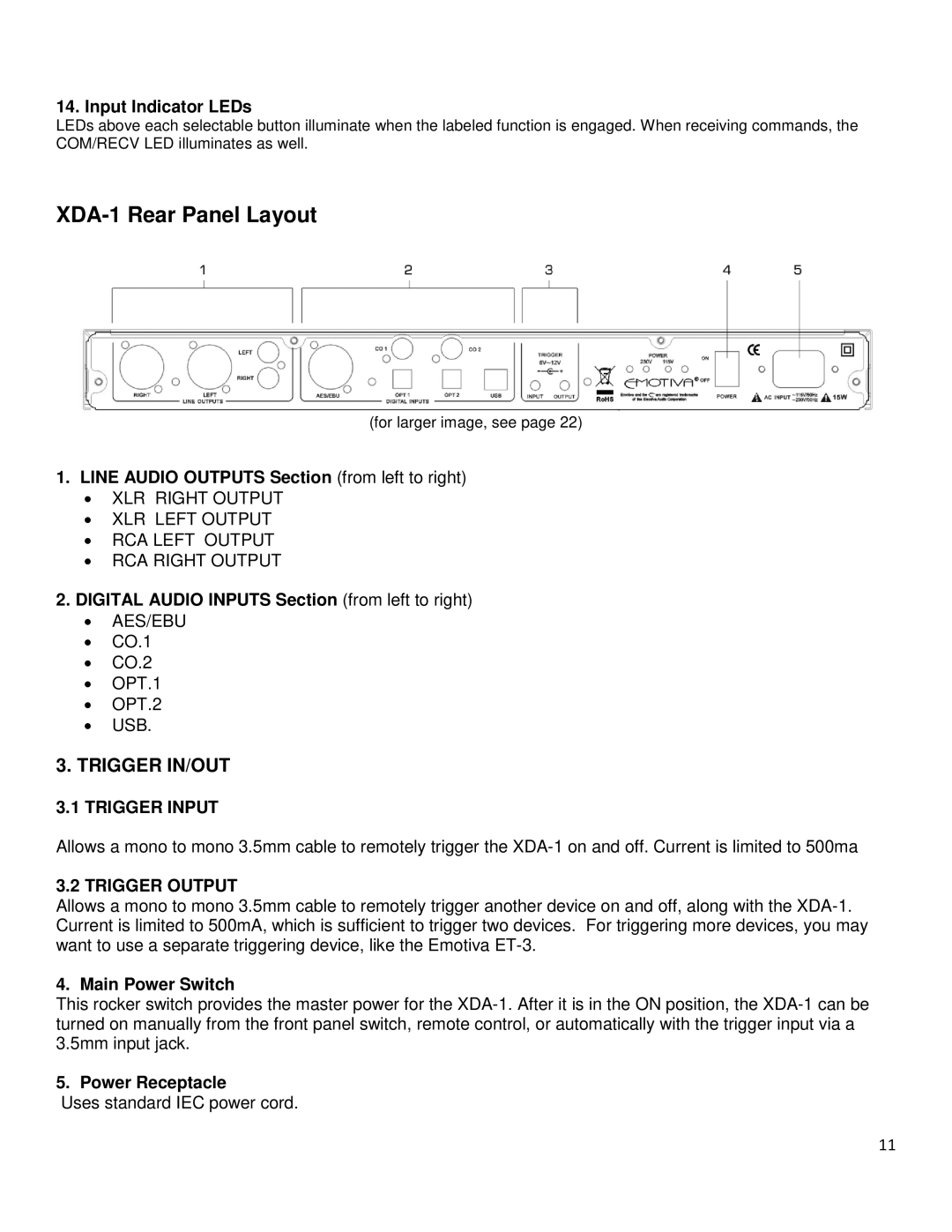
XDA-1 Rear Panel Layout
(for larger image, see page 22)
1.LINE AUDIO OUTPUTS Section (from left to right)
•XLR RIGHT OUTPUT
•XLR LEFT OUTPUT
•RCA LEFT OUTPUT
•RCA RIGHT OUTPUT
2.DIGITAL AUDIO INPUTS Section (from left to right)
•AES/EBU
•CO.1
•CO.2
•OPT.1
•OPT.2
•USB.
3.TRIGGER IN/OUT
3.1 TRIGGER INPUT
Allows a mono to mono 3.5mm cable to remotely trigger the
3.2 TRIGGER OUTPUT
Allows a mono to mono 3.5mm cable to remotely trigger another device on and off, along with the
4. Main Power Switch
This rocker switch provides the master power for the
5. Power Receptacle
Uses standard IEC power cord.
11