Specifications
Model | | CIVF-25 |
Input BTU/HR (KW/H) Max. (LP/NAT) | 25,000 ( 7.3) |
BTU/HR (KW/H) Min. LP | 18,000 (5.3) |
BTU/HR (KW/H) Min. Nat. | 17,000 (5.0) |
Height | | 27 3/4" (70.5cm) |
Width | | 25 1/2" (64.8cm) |
Depth | | 15 1/2" (39.4cm) |
Gas Inlet | | 3/8" (9.5mm) |
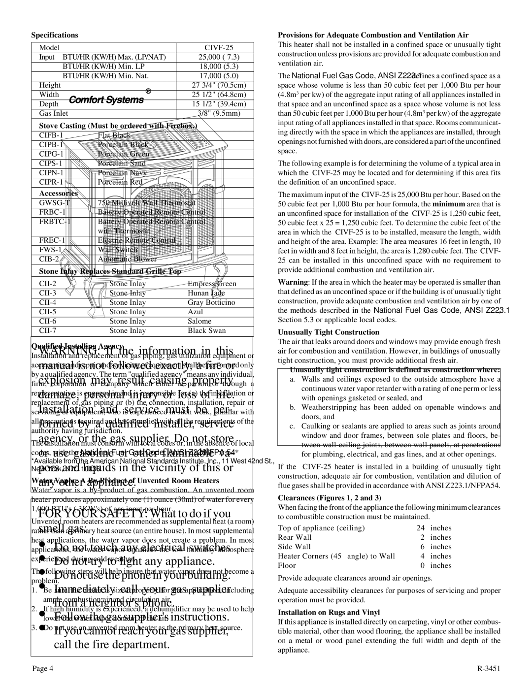
Stove Casting (Must be ordered with Firebox.) |
| | |
CIFB-1 | Flat Black | |
CIPB-1 | Porcelain Black | |
CIPG-1 | Porcelain Green | |
CIPS-1 | Porcelain Sand | |
CIPN-1 | Porcelain Navy | |
CIPR-1 | Porcelain Red | |
Accessories | | |
| | |
GWSG-T | 750 Millivolt Wall Thermostat |
FRBC-1 | Battery Operated Remote Control |
FRBTC-1 | Battery Operated Remote Control |
| with Thermostat | |
FREC-1 | Electric Remote Control | |
FWS-1 | Wall Switch | |
CIB-2 | Automatic Blower | |
Stone Inlay Replaces Standard Grille Top
CII-2 | Stone Inlay | Empress Green |
CII-3 | Stone Inlay | Hunan Jade |
CII-4 | Stone Inlay | Gray Botticino |
CII-5 | Stone Inlay | Azul |
CII-6 | Stone Inlay | Salome |
CII-7 | Stone Inlay | Black Swan |
Qualified Installing Agency
Installation and replacement of gas piping, gas utilization equipment or accessories and repair and servicing of equipment shall be performed only by a qualified agency. The term "qualified agency" means any individual, firm, corporation or company which either in person or through a representative is engaged in and is responsible for (a) the installation or replacement of gas piping or (b) the connection, installation, repair or servicing of equipment, who is experienced in such work, familiar with all precautions required and has complied with all the requirements of the authority having jurisdiction.
The installation must conform with local codes or, in the absence of local codes, with the National Fuel Gas Code, ANSI Z223.1/NFPA 54.*
*Available from the American National Standards Institute, Inc., 11 West 42nd St., New York, N.Y. 10036.
Water Vapor: A By-Product of Unvented Room Heaters
Water vapor is a by-product of gas combustion. An unvented room heater produces approximately one (1) ounce (30ml) of water for every 1,000 BTU's (.3KW's) of gas input per hour.
Unvented room heaters are recommended as supplemental heat (a room) rather than a primary heat source (an entire house). In most supplemental heat applications, the water vapor does not create a problem. In most applications, the water vapor enhances the low humidity atmosphere experienced during cold weather.
The following steps will help insure that water vapor does not become a problem.
1.Be sure the heater is sized properly for the application, including ample combustion air and circulation air.
2.If high humidity is experienced, a dehumidifier may be used to help lower the water vapor content of the air.
3.Do not use an unvented room heater as the primary heat source.
Page 4
Provisions for Adequate Combustion and Ventilation Air
This heater shall not be installed in a confined space or unusually tight construction unless provisions are provided for adequate combustion and ventilation air.
The National Fuel Gas Code, ANSI Z223.1 defines a confined space as a space whose volume is less than 50 cubic feet per 1,000 Btu per hour (4.8m3 per kw) of the aggregate input rating of all appliances installed in that space and an unconfined space as a space whose volume is not less than 50 cubic feet per 1,000 Btu per hour (4.8m3 per kw) of the aggregate input rating of all appliances installed in that space. Rooms communicat- ing directly with the space in which the appliances are installed, through openings not furnished with doors, are considered a part of the unconfined space.
The following example is for determining the volume of a typical area in which the CIVF-25 may be located and for determining if this area fits the definition of an unconfined space.
The maximum input of the CIVF-25 is 25,000 Btu per hour. Based on the 50 cubic feet per 1,000 Btu per hour formula, the minimum area that is an unconfined space for installation of the CIVF-25 is 1,250 cubic feet, 50 cubic feet x 25 = 1,250 cubic feet. To determine the cubic feet of the area in which the CIVF-25 is to be installed, measure the length, width and height of the area. Example: The area measures 16 feet in length, 10 feet in width and 8 feet in height, the area is 1,280 cubic feet. The CIVF- 25 can be installed in this unconfined space with no requirement to provide additional combustion and ventilation air.
Warning: If the area in which the heater may be operated is smaller than that defined as an unconfined space or if the building is of unusually tight construction, provide adequate combustion and ventilation air by one of the methods described in the National Fuel Gas Code, ANSI Z223.1, Section 5.3 or applicable local codes.
Unusually Tight Construction
The air that leaks around doors and windows may provide enough fresh air for combustion and ventilation. However, in buildings of unusually tight construction, you must provide additional fresh air.
Unusually tight construction is defined as construction where:
a.Walls and ceilings exposed to the outside atmosphere have a continuous water vapor retarder with a rating of one perm or less with openings gasketed or sealed, and
b.Weatherstripping has been added on openable windows and doors, and
c.Caulking or sealants are applied to areas such as joints around window and door frames, between sole plates and floors, be- tween wall-ceiling joints, between wall panels, at penetrations for plumbing, electrical, and gas lines, and at other openings.
If the CIVF-25 heater is installed in a building of unusually tight construction, adequate air for combustion, ventilation and dilution of flue gases shall be provided in accordance with ANSI Z223.1/NFPA54.
Clearances (Figures 1, 2 and 3)
When facing the front of the appliance the following minimum clearances to combustible construction must be maintained.
Top of appliance (ceiling) | 24 | inches |
Rear Wall | 2 | inches |
Side Wall | 6 | inches |
Heater Corners (45° angle) to Wall | 4 | inches |
Floor | 0 | inches |
Provide adequate clearances around air openings.
Adequate accessibility clearances for purposes of servicing and proper operation must be provided.
Installation on Rugs and Vinyl
If this appliance is installed directly on carpeting, vinyl or other combus- tible material, other than wood flooring, the appliance shall be installed on a metal or wood panel extending the full width and depth of the appliance.
R-3451