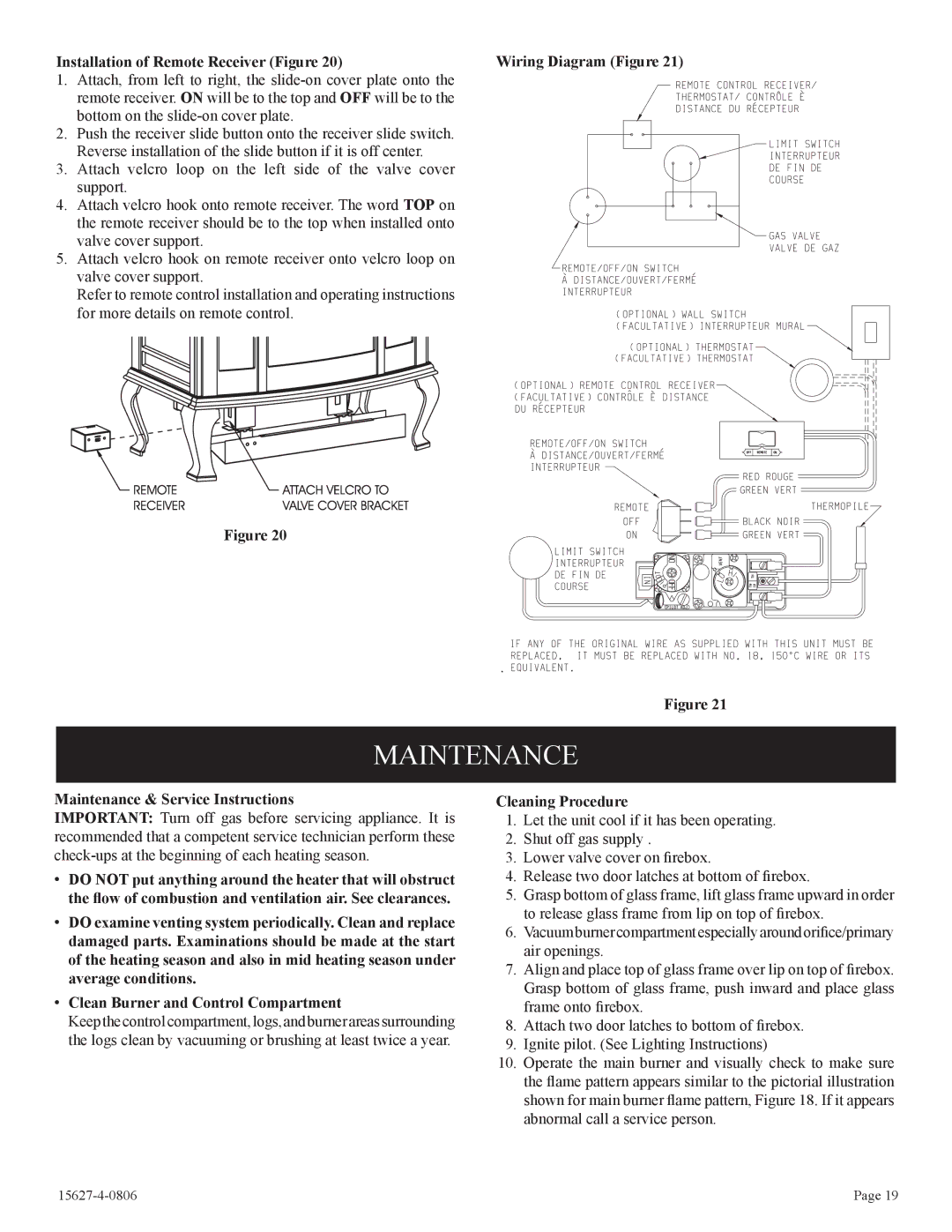
Installation of Remote Receiver (Figure 20) | Wiring Diagram (Figure 21) |
1.Attach, from left to right, the
2.Push the receiver slide button onto the receiver slide switch. Reverse installation of the slide button if it is off center.
3.Attach velcro loop on the left side of the valve cover support.
4.Attach velcro hook onto remote receiver. The word TOP on the remote receiver should be to the top when installed onto valve cover support.
5.Attach velcro hook on remote receiver onto velcro loop on valve cover support.
Refer to remote control installation and operating instructions for more details on remote control.
Figure 20
.
Figure 21
MAINTENANCE
Maintenance & Service Instructions
IMPORTANT: Turn off gas before servicing appliance. It is recommended that a competent service technician perform these
•DO NOT put anything around the heater that will obstruct the flow of combustion and ventilation air. See clearances.
•DO examine venting system periodically. Clean and replace damaged parts. Examinations should be made at the start of the heating season and also in mid heating season under average conditions.
•Clean Burner and Control Compartment
Keep the control compartment, logs, and burner areas surrounding the logs clean by vacuuming or brushing at least twice a year.
Cleaning Procedure
1.Let the unit cool if it has been operating.
2.Shut off gas supply .
3.Lower valve cover on firebox.
4.Release two door latches at bottom of firebox.
5.Grasp bottom of glass frame, lift glass frame upward in order to release glass frame from lip on top of firebox.
6.Vacuumburnercompartmentespeciallyaroundorifice/primary air openings.
7.Align and place top of glass frame over lip on top of firebox. Grasp bottom of glass frame, push inward and place glass frame onto firebox.
8.Attach two door latches to bottom of firebox.
9.Ignite pilot. (See Lighting Instructions)
10.Operate the main burner and visually check to make sure the flame pattern appears similar to the pictorial illustration shown for main burner flame pattern, Figure 18. If it appears abnormal call a service person.
| Page 19 |
