OPTIONAL BLOWER INSTALLATION INSTRUCTIONS

GWTB-2 FOR MODELS

GWT-25 (SG, RB), GWT-35 (SG, RB), GWT-50 (SG, RB)

Installing Blower Using Three-Prong Plug

1.Install furnace according to Installation Instructions and Owner's Manual.

2.Refer to Drawing for measurements to locate (2) mounting holes on wall surface above furnace.

On Solid Wall

3.After locating mounting holes, attach (2) #10 x 1 1/2" screws provided in blower kit into wall. Do not completely tighten screwheads to

wall, leave a 7/16" gap between screwheads and wall.

On Sheet Rock Wall

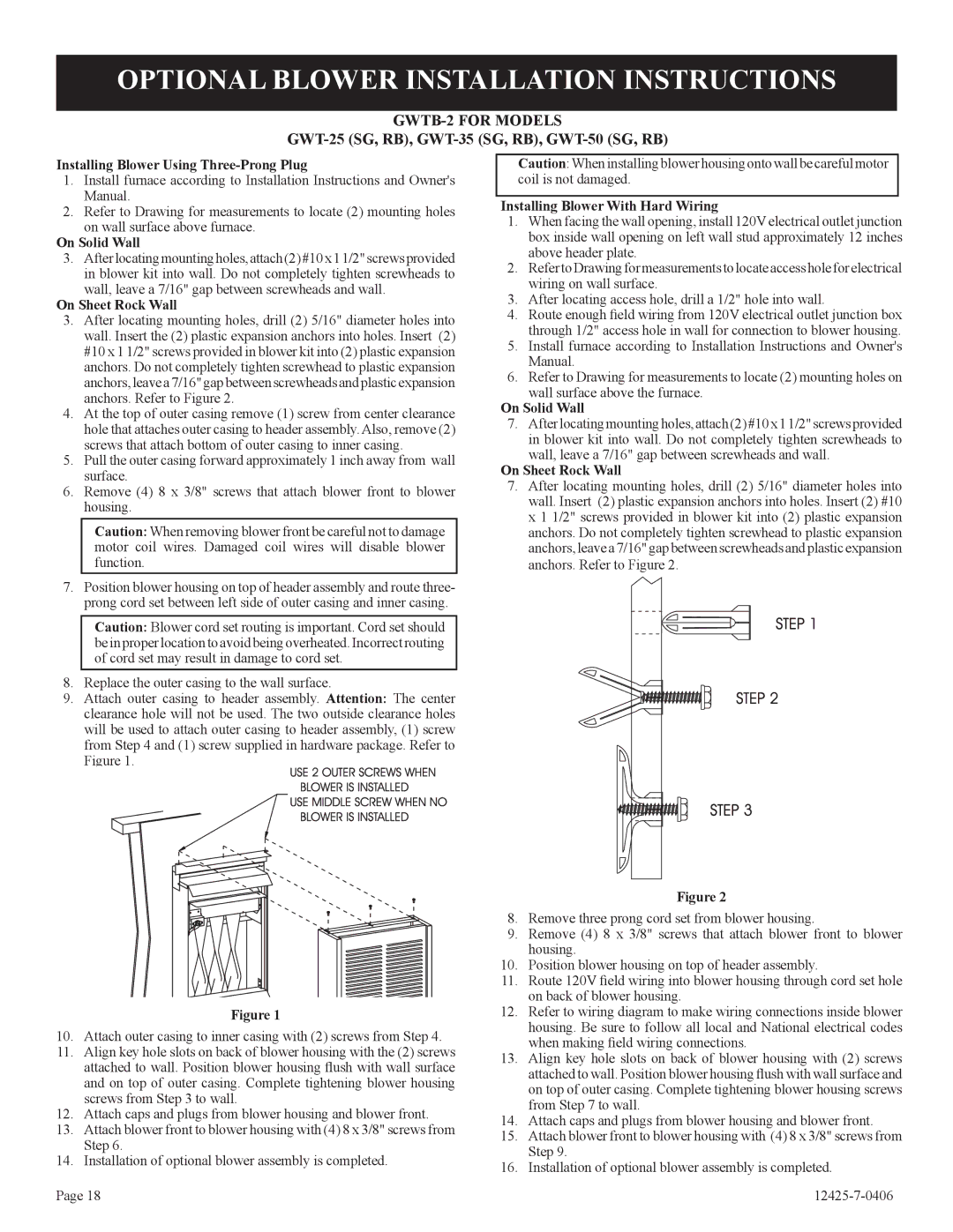
3.After locating mounting holes, drill (2) 5/16" diameter holes into wall. Insert the (2) plastic expansion anchors into holes. Insert (2) #10 x 1 1/2" screws provided in blower kit into (2) plastic expansion anchors. Do not completely tighten screwhead to plastic expansion anchors, leave a 7/16" gap between screwheads and plastic expansion anchors. Refer to Figure 2.

4.At the top of outer casing remove (1) screw from center clearance hole that attaches outer casing to header assembly. Also, remove (2) screws that attach bottom of outer casing to inner casing.

5.Pull the outer casing forward approximately 1 inch away from wall surface.

6.Remove (4) 8 x 3/8" screws that attach blower front to blower housing.

Caution: When removing blower front be careful not to damage motor coil wires. Damaged coil wires will disable blower function.

7.Position blower housing on top of header assembly and route three- prong cord set between left side of outer casing and inner casing.

Caution: Blower cord set routing is important. Cord set should be in proper location to avoid being overheated. Incorrect routing of cord set may result in damage to cord set.

8.Replace the outer casing to the wall surface.

9.Attach outer casing to header assembly. Attention: The center clearance hole will not be used. The two outside clearance holes will be used to attach outer casing to header assembly, (1) screw from Step 4 and (1) screw supplied in hardware package. Refer to Figure 1.

Figure 1

10. Attach outer casing to inner casing with (2) screws from Step 4.

11.Align key hole slots on back of blower housing with the (2) screws attached to wall. Position blower housing flush with wall surface and on top of outer casing. Complete tightening blower housing screws from Step 3 to wall.

12.Attach caps and plugs from blower housing and blower front.

13.Attach blower front to blower housing with (4) 8 x 3/8" screws from

Step 6.

14. Installation of optional blower assembly is completed.

Page 18

Caution: When installing blower housing onto wall be careful motor coil is not damaged.

Installing Blower With Hard Wiring

1.When facing the wall opening, install 120V electrical outlet junction box inside wall opening on left wall stud approximately 12 inches above header plate.

2.Refer to Drawing for measurements to locate access hole for electrical wiring on wall surface.

3.After locating access hole, drill a 1/2" hole into wall.

4.Route enough field wiring from 120V electrical outlet junction box through 1/2" access hole in wall for connection to blower housing.

5.Install furnace according to Installation Instructions and Owner's Manual.

6.Refer to Drawing for measurements to locate (2) mounting holes on wall surface above the furnace.

On Solid Wall

7.After locating mounting holes, attach (2) #10 x 1 1/2" screws provided in blower kit into wall. Do not completely tighten screwheads to

wall, leave a 7/16" gap between screwheads and wall.

On Sheet Rock Wall

7.After locating mounting holes, drill (2) 5/16" diameter holes into wall. Insert (2) plastic expansion anchors into holes. Insert (2) #10 x 1 1/2" screws provided in blower kit into (2) plastic expansion anchors. Do not completely tighten screwhead to plastic expansion anchors, leave a 7/16" gap between screwheads and plastic expansion anchors. Refer to Figure 2.

Figure 2

8.Remove three prong cord set from blower housing.

9.Remove (4) 8 x 3/8" screws that attach blower front to blower

housing.

10. Position blower housing on top of header assembly.

11. Route 120V field wiring into blower housing through cord set hole on back of blower housing.

12. Refer to wiring diagram to make wiring connections inside blower housing. Be sure to follow all local and National electrical codes when making field wiring connections.

13.Align key hole slots on back of blower housing with (2) screws attached to wall. Position blower housing flush with wall surface and on top of outer casing. Complete tightening blower housing screws from Step 7 to wall.

14.Attach caps and plugs from blower housing and blower front.

15.Attach blower front to blower housing with (4) 8 x 3/8" screws from

Step 9.

16. Installation of optional blower assembly is completed.

12425-7-0406

Page 18
Image 18
Empire Products GWT-35-2, RB), GWT-25-2 Optional Blower Installation Instructions, GWTB-2 for Models

GWT-35-2, RB), GWT-25-2 specifications

Empire Products is renowned for its commitment to quality and innovation, particularly in the realm of heating solutions. Among their extensive range, the GWT-35-2 and GWT-25-2 gas-fired wall heaters stand out as exceptional choices for both residential and commercial applications.

The Empire GWT-35-2 is designed to deliver a powerful heating solution, boasting an impressive heat output. With an efficiency rating that ensures optimal warmth while minimizing energy consumption, this model is perfect for larger spaces that require consistent and reliable heating. Its sleek design allows it to seamlessly blend into various room aesthetics, while the multiple installation options make it versatile enough to meet varying layouts and preferences.

On the other hand, the GWT-25-2 is tailored for slightly smaller areas, yet it does not compromise on performance. This model provides ample heating efficiency and is well-suited for those looking to maintain a cozy atmosphere in modest-sized rooms. The unit’s compact form factor allows for easy installation without occupying too much wall space, making it an ideal option for residential settings.

Both models utilize advanced technologies that contribute to their superior performance. The state-of-the-art electronic ignition system in the GWT series ensures reliable startups, while the built-in thermostat provides precise temperature control. Users can easily adjust settings to their comfort levels, enhancing overall user satisfaction. Additionally, the heaters are equipped with innovative safety features such as automatic shut-off mechanisms, making them a safe choice for any environment.

Another key characteristic of the GWT-35-2 and GWT-25-2 is their fuel efficiency. By utilizing natural gas or propane, these units are designed to reduce energy costs without sacrificing heating quality. The durable construction of both models guarantees longevity and resilience, meaning customers can expect years of dependable service.

In summary, Empire Products' GWT-35-2 and GWT-25-2 wall heaters exemplify cutting-edge heating technology. Their combination of efficiency, performance, and safety features makes them a reliable choice for anyone in need of effective heating solutions, whether in a home or a commercial space. With Empire's commitment to quality, customers can feel confident in their investment in these powerful heating units.