GWT-35-2, RB), GWT-25-2 specifications
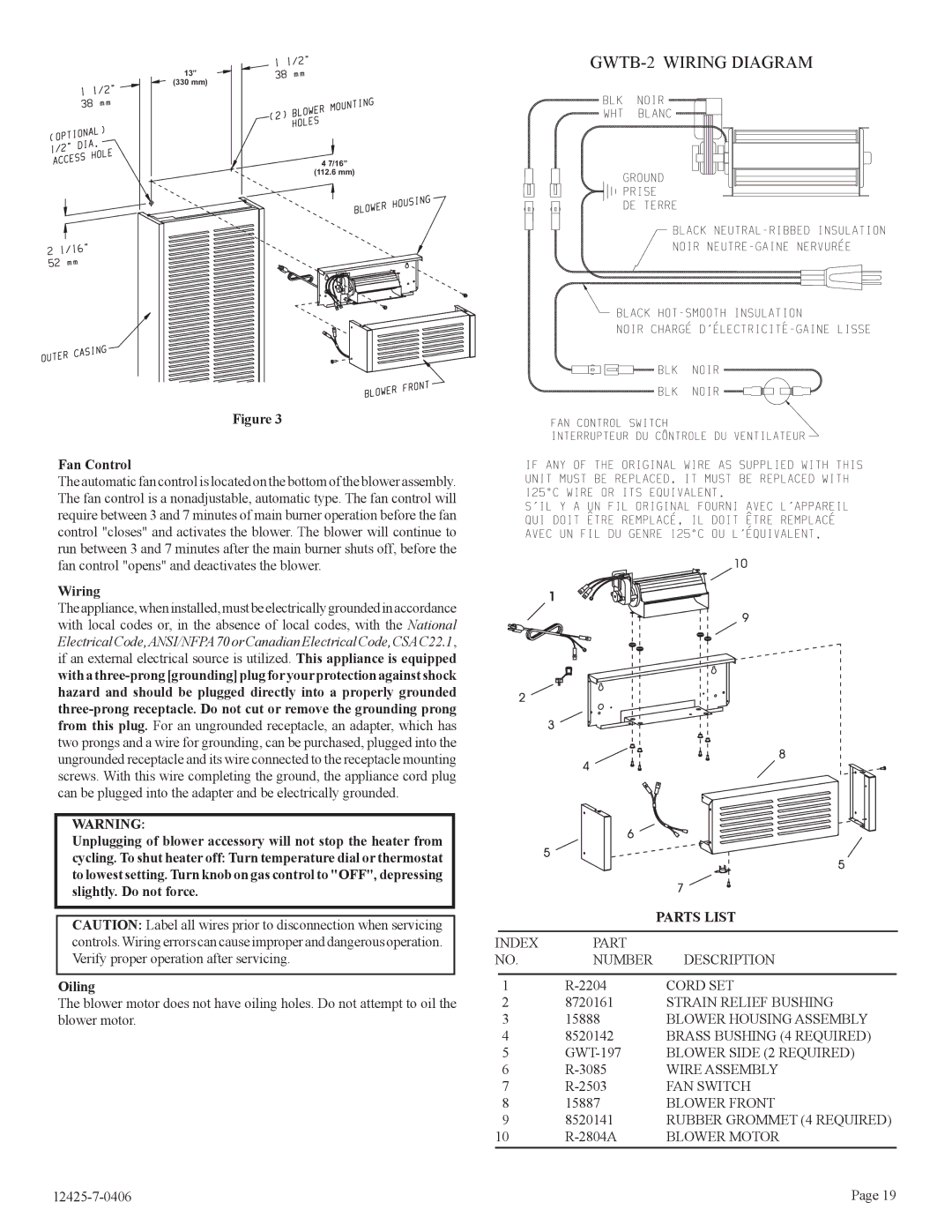
Empire Products is renowned for its commitment to quality and innovation, particularly in the realm of heating solutions. Among their extensive range, the GWT-35-2 and GWT-25-2 gas-fired wall heaters stand out as exceptional choices for both residential and commercial applications.The Empire GWT-35-2 is designed to deliver a powerful heating solution, boasting an impressive heat output. With an efficiency rating that ensures optimal warmth while minimizing energy consumption, this model is perfect for larger spaces that require consistent and reliable heating. Its sleek design allows it to seamlessly blend into various room aesthetics, while the multiple installation options make it versatile enough to meet varying layouts and preferences.
On the other hand, the GWT-25-2 is tailored for slightly smaller areas, yet it does not compromise on performance. This model provides ample heating efficiency and is well-suited for those looking to maintain a cozy atmosphere in modest-sized rooms. The unit’s compact form factor allows for easy installation without occupying too much wall space, making it an ideal option for residential settings.
Both models utilize advanced technologies that contribute to their superior performance. The state-of-the-art electronic ignition system in the GWT series ensures reliable startups, while the built-in thermostat provides precise temperature control. Users can easily adjust settings to their comfort levels, enhancing overall user satisfaction. Additionally, the heaters are equipped with innovative safety features such as automatic shut-off mechanisms, making them a safe choice for any environment.
Another key characteristic of the GWT-35-2 and GWT-25-2 is their fuel efficiency. By utilizing natural gas or propane, these units are designed to reduce energy costs without sacrificing heating quality. The durable construction of both models guarantees longevity and resilience, meaning customers can expect years of dependable service.
In summary, Empire Products' GWT-35-2 and GWT-25-2 wall heaters exemplify cutting-edge heating technology. Their combination of efficiency, performance, and safety features makes them a reliable choice for anyone in need of effective heating solutions, whether in a home or a commercial space. With Empire's commitment to quality, customers can feel confident in their investment in these powerful heating units.

