1.GENERAL INFORMATION

a.Your heater comes fully assembled and is tested at the factory for proper gas and input as stated on the name plate.

b.Before proceeding with the installation, be sure to inspect for damages. Freight company must be noti- fied of any damages and request that an inspection be made by the freight company. HEAT STAR will send replacement parts for damaged parts only after receiv- ing a signed inspection report to prove the liability of the freight company.

c.Do not attempt to operate heater with any other gas than that indicated on the heater name plate.

d.The installation of heater must conform with local building codes or, in absence of local codes, with the National Fuel Gas Code, ANSI Z223.1a/NFPA54. In Canada, refer to Can 1-B146.1 and B149.2.

e.Plugged 1/8” N.P.T. Test Gage Connection is located on the Heater Gas Control or a ¼” N.P.T. Connection is located on the outside of the Cast Venturi.

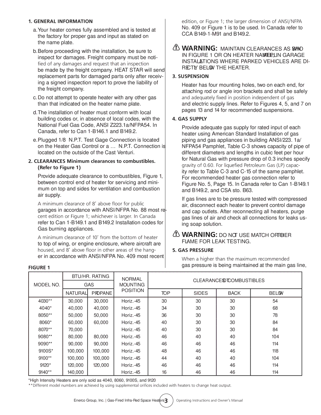
2.CLEARANCES Minimum clearances to combustibles. (Refer to Figure 1)

Provide adequate clearance to combustibles, Figure 1, between control end of heater for servicing and mini- mum on top and sides for ventilation and combustion air supply.

A minimum clearance of 8’ above floor for public garages in accordance with ANSI/NFPA No. 88 most re- cent edition or Figure 1; whichever is larger. In Canada refer to Can 1-B149.1 and B149.2 Installation codes for Gas burning appliances.

A minimum clearance of 10’ from the bottom of heater to top of wing, or engine enclosure, where aircraft are housed, and 8’ above floor in other areas of the hang- er in accordance with ANSI/NFPA No. 409 most recent

Figure 1

edition, or Figure 1; the larger dimension of ANSI/NFPA No. 409 or Figure 1 is to be used. In Canada refer to CCA B149-1-M91 and B149.2.

WARNING: Maintain clearances as shown in Figure 1 or on heater nameplate, in garage installations where parked vehicles are di- rectly below the heater.

3. SUSPENSION

Heater has four mounting holes, two on each end, for attaching rod or angle iron brackets and shall be safely and adequately fixed in position independent of gas and electric supply lines. Refer to Figures 4, 5, and 7 on pages 13 and 14 for recommended suspensions.

4. GAS SUPPLY

Provide adequate gas supply for rated input of each heater using American Standard Installation of gas piping and gas appliances in building ANSI/223. 1a/ NFPA54 Pamphlet, Table C-3 shows capacity of pipe of different diameters and lengths in cubic feet per hour for Natural Gas with pressure drop of 0.3 inches specify gravity of 0.60. For liquefied Petroleum Gas (LP) capac- ity refer to Table C-3 and C-15 of the same pamphlet. For recommended heater gas connection refer to Figure No. 5, Page 15. In Canada refer to Can 1-B149.1 and B149.2, and CSA sto. B63.

If gas lines are to be pressure tested with compressed air, disconnect each heater to prevent control damage and cap outlets. After reconnecting all heaters, purge gas lines of air and check all connections for leaks us- ing soap solution.

WARNING: Do NOT USE MATCH OR OTHER FLAME FOR LEAK TESTING.

5. GAS PRESSURE

When a higher than the maximum recommended gas pressure is being maintained at the main gas line,


BTU/HR. RATING

NORMAL


CLEARANCES TO COMBUSTIBLES


MODEL NO.

GAS

MOUNTING


POSITION


NATURAL

PROPANE

TOP

SIDES

BACK


BELOW


4030**

30,000

30,000

Horiz.-45°

30”

30”

30”


54”

4040*

40,000

40,000

Horiz.-45°

34”

30”

30”


68”

8050**

50,000

50,000

Horiz.-45°

36”

30”

30”


78”

8060*

60,000

60,000

Horiz.-45°

40”

30”

30”


84”

8070**

70,000

Horiz.-45°

40”

30”

30”


84”

9080**

80,000

80,000

Horiz.-45°

46”

40”

40”


104”

9090**

90,000

90,000

Horiz.-45°

46”

46”

46”


114”

9100S*

100,000

100,000

Horiz.-45°

48”

46”

46”


118”

9100**

100,000

100,000

Horiz.-45°

44”

40”

40”


104”

9120*

120,000

120,000

Horiz.-45°

46”

46”

46”


114”

9140**

140,000

Horiz.-45°

16”

46”

46”


114”

*High Intensity Heaters are only sold as 4040, 8060, 9100S, and 9120

**Different model numbers are achieved by using supplemental orifices included with heaters to change heat output.

Enerco Group, Inc. Gas-Fired Infra-Red Space Heaters

3

Operating Instructions and Owner’s Manual

Page 3
Image 3
Enerco HS9120, HS4040, HS8060, HS9100S owner manual General Information, Suspension, GAS Supply, GAS Pressure

HS8060, HS9120, HS9100S, HS4040 specifications

The Enerco HS9100S, HS9120, HS4040, and HS8060 are a range of high-performance space heaters designed to provide efficient heating solutions for various applications. Each model comes with specific features and technologies that cater to different heating needs while ensuring energy efficiency and user comfort.

The HS9100S is renowned for its robust build and powerful heating capacity. With a heat output of up to 9,000 BTUs, it effectively warms up spaces in a matter of moments. One of its standout features is the precise thermostat control that allows users to set their desired temperature easily. Additionally, the HS9100S has a safety shut-off system that activates in case of overheating, making it a dependable choice for homes and garages.

The HS9120 model builds on the features of the HS9100S while integrating advanced infrared technology. This unit not only heats the air but also warms objects and people in the room, creating a more comfortable environment. With a sleek design, the HS9120 is both practical and aesthetically pleasing. The adjustable heat settings provide versatility, enabling users to customize their heating experience based on different conditions.

The HS4040 is tailored for those seeking portability without sacrificing performance. Weighing significantly less than its counterparts, this model is easy to move between locations, making it ideal for workshops or outdoor use. The HS4040 features a built-in handle and compact design for enhanced mobility. Despite its smaller size, this unit delivers an output of up to 4,000 BTUs and includes a reliable safety feature to prevent accidental ignition.

Lastly, the HS8060 stands out for its user-friendly interface. It includes an LED display that provides real-time temperature readings, along with a remote control option for added convenience. The HS8060 model is equipped with energy-saving modes, allowing for reduced power consumption when heating is not required at full capacity. Its versatile design makes it suitable for any room, including living spaces and office areas.

In summary, the Enerco HS9100S, HS9120, HS4040, and HS8060 represent a commitment to quality and efficiency in portable heating solutions. Each model offers its unique set of features, making them suitable for a range of heating applications, ensuring warmth and comfort during cold months. With a focus on safety, efficiency, and user convenience, these units are excellent choices for anyone seeking reliable heating options.