3002503 11.06
4.4 Installing a Proven Draft Switch
A safety system must be interlocked with the appliance. The safety system could utilize a Proven Draft Switch (PDS-1), a thermal switch, a flow switch or a sail switch. The device must be interlocked with the heating appliance(s) so it shuts down in case of insufficient draft, fan failure or power failure. Please refer to
the PDS Installation Manual for wiring instructions.
If the installation includes an EBC12 or EBC 30 Fan Control, a PDS-1 is not required as the function is integrated in the control.
For more information about alternative safety system, please consult EXHAUSTO.
4.5 Installation of Stack Probe for PDS Function
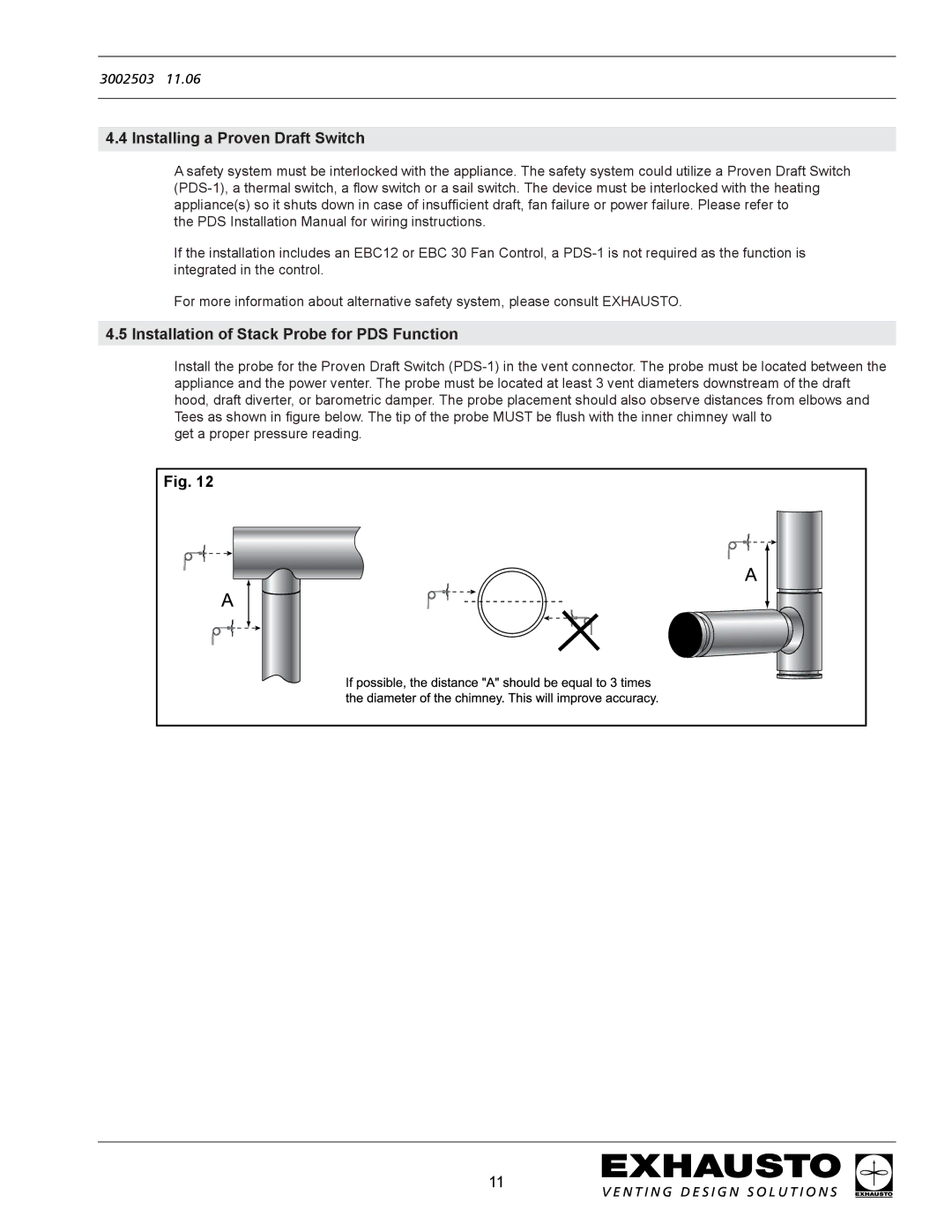
Install the probe for the Proven Draft Switch (PDS-1) in the vent connector. The probe must be located between the appliance and the power venter. The probe must be located at least 3 vent diameters downstream of the draft hood, draft diverter, or barometric damper. The probe placement should also observe distances from elbows and Tees as shown in figure below. The tip of the probe MUST be flush with the inner chimney wall to
get a proper pressure reading.
11