C2RPS-POE Overview
The purpose of the C2RPS‐POE is to provide power backup to an Enterasys SecureStack C2 PoE‐compliant stackable switch. If for some reason the switch looses power from its internal power supply, the C2RPS‐POE can provide up to 500 Watts maximum operating power to support switch operation and the 48 Vdc cessary to support 48 Vdc/data connections to PDs (Powered Devices).
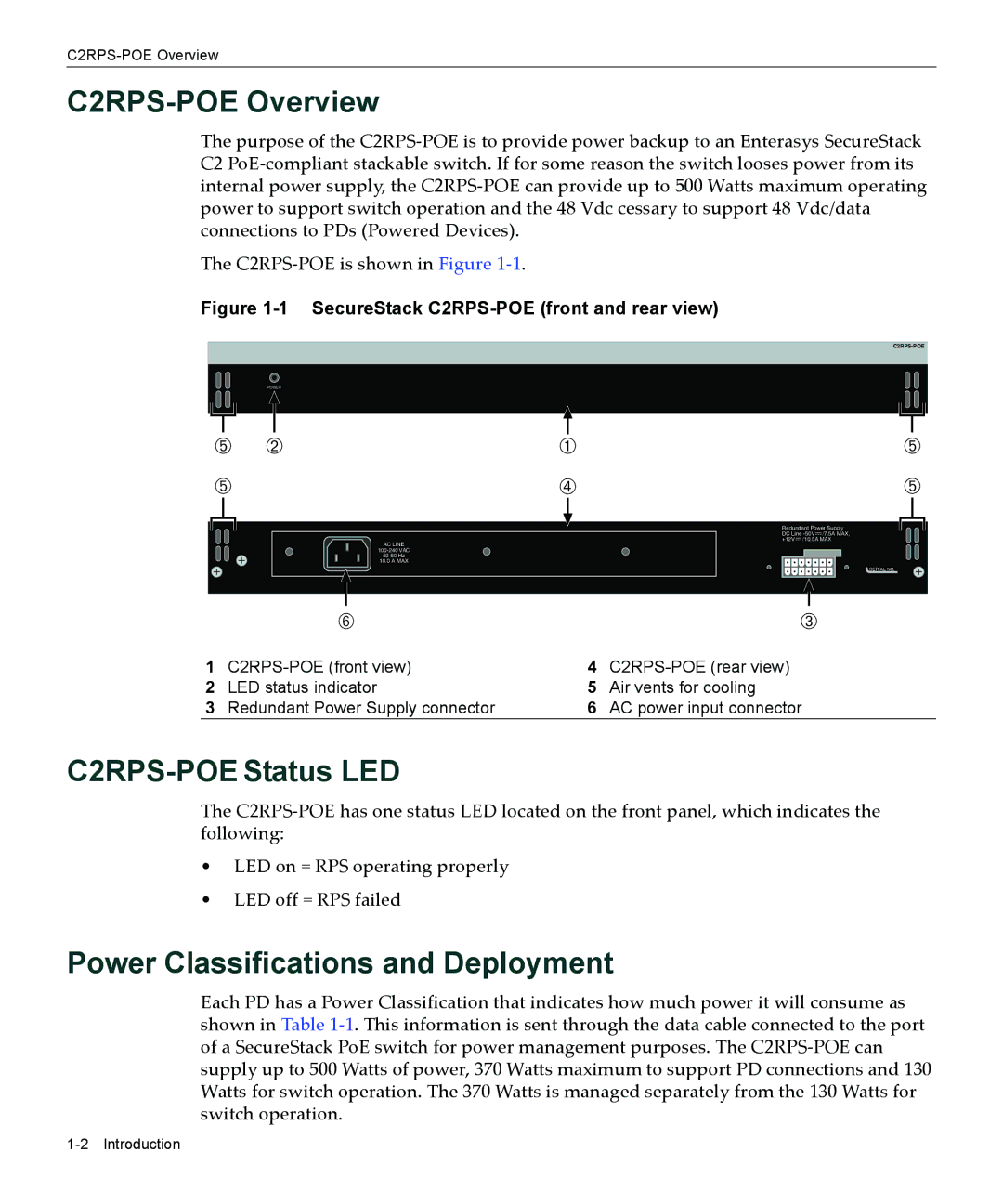
The C2RPS‐POE is shown in Figure 1‐1.
Figure 1-1 SecureStack C2RPS-POE (front and rear view)
POWER
|
|
|
|
|
|
|
|
|
|
|
|
|
|
|
|
Ä | Á | À | Ä | ||||
Ä |
|
| Ã | Ä | |||
AC LINE
10.0 A MAX
Redundant Power Supply
DC Line
+12V /10.5A MAX
SERIAL NO.
| Å |
| Â |
1 | 4 | ||
2 | LED status indicator | 5 | Air vents for cooling |
3 | Redundant Power Supply connector | 6 | AC power input connector |
C2RPS-POE Status LED
The C2RPS‐POE has one status LED located on the front panel, which indicates the following:
•LED on = RPS operating properly
•LED off = RPS failed
Power Classifications and Deployment
Each PD has a Power Classification that indicates how much power it will consume as shown in Table 1‐1. This information is sent through the data cable connected to the port of a SecureStack PoE switch for power management purposes. The C2RPS‐POE can supply up to 500 Watts of power, 370 Watts maximum to support PD connections and 130 Watts for switch operation. The 370 Watts is managed separately from the 130 Watts for switch operation.