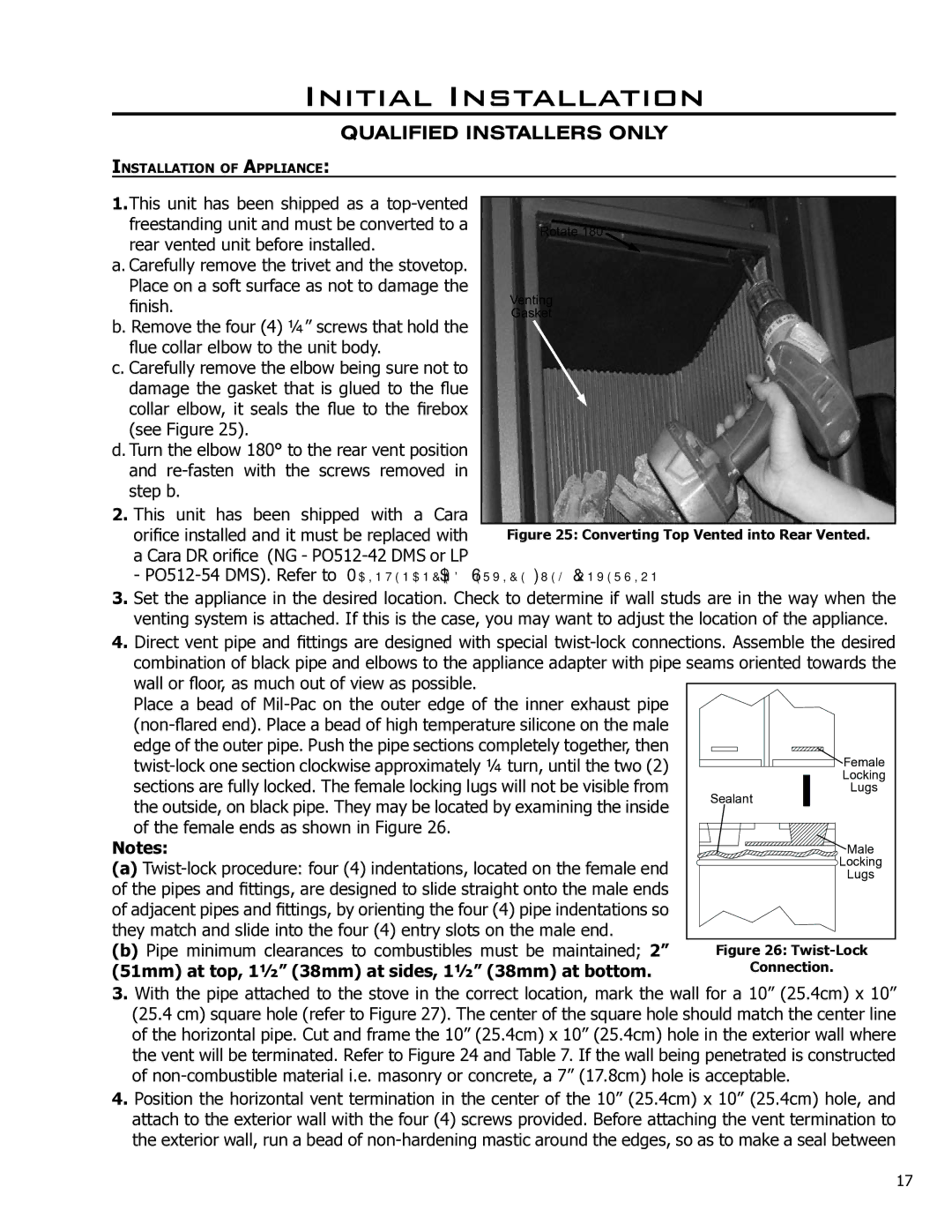
Figure 25: Converting Top Vented into Rear Vented.

Initial Installation

QUALIFIED INSTALLERS ONLY

INSTALLATION OF APPLIANCE:

1.This unit has been shipped as a top-vented freestanding unit and must be converted to a

rear vented unit before installed.

a. Carefully remove the trivet and the stovetop. Place on a soft surface as not to damage the finish.

b. Remove the four (4) 1⁄4” screws that hold the flue collar elbow to the unit body.

c. Carefully remove the elbow being sure not to damage the gasket that is glued to the flue collar elbow, it seals the flue to the firebox (see Figure 25).

d. Turn the elbow 180° to the rear vent position and re-fasten with the screws removed in step b.

2.This unit has been shipped with a Cara

orifice installed and it must be replaced with a Cara DR orifice (NG - PO512-42 DMS or LP

- PO512-54 DMS). Refer to MAINTENANCE AND SERVICE - FUEL CONVERSION.

3.Set the appliance in the desired location. Check to determine if wall studs are in the way when the venting system is attached. If this is the case, you may want to adjust the location of the appliance.

4.Direct vent pipe and fittings are designed with special twist-lock connections. Assemble the desired combination of black pipe and elbows to the appliance adapter with pipe seams oriented towards the wall or floor, as much out of view as possible.

Place a bead of Mil-Pac on the outer edge of the inner exhaust pipe


(non-flared end). Place a bead of high temperature silicone on the male


edge of the outer pipe. Push the pipe sections completely together, then


Female


twist-lock one section clockwise approximately 1⁄4 turn, until the two (2)


sections are fully locked. The female locking lugs will not be visible from


Locking

Sealant


Lugs

the outside, on black pipe. They may be located by examining the inside


of the female ends as shown in Figure 26.


Notes:


Male


(a) Twist-lock procedure: four (4) indentations, located on the female end


Locking


of the pipes and fittings, are designed to slide straight onto the male ends


Lugs


of adjacent pipes and fittings, by orienting the four (4) pipe indentations so


they match and slide into the four (4) entry slots on the male end.


(b) Pipe minimum clearances to combustibles must be maintained; 2”


Figure 26: Twist-Lock

(51mm) at top, 11⁄2” (38mm) at sides, 11⁄2” (38mm) at bottom.


Connection.

3.With the pipe attached to the stove in the correct location, mark the wall for a 10” (25.4cm) x 10” (25.4 cm) square hole (refer to Figure 27). The center of the square hole should match the center line of the horizontal pipe. Cut and frame the 10” (25.4cm) x 10” (25.4cm) hole in the exterior wall where the vent will be terminated. Refer to Figure 24 and Table 7. If the wall being penetrated is constructed of non-combustible material i.e. masonry or concrete, a 7” (17.8cm) hole is acceptable.

4.Position the horizontal vent termination in the center of the 10” (25.4cm) x 10” (25.4cm) hole, and attach to the exterior wall with the four (4) screws provided. Before attaching the vent termination to the exterior wall, run a bead of non-hardening mastic around the edges, so as to make a seal between

17

Page 17
Image 17
Enviro 50-1628 owner manual 51mm at top, 11⁄2 38mm at sides, 11⁄2 38mm at bottom, Twist-Lock

50-1628 specifications

Enviro 50-1628 is a revolutionary piece of technology designed to enhance sustainability and efficiency in various applications, particularly in the field of environmental management. This advanced system focuses on achieving ecological balance while delivering high performance, making it a valuable asset for industries aiming for greener operations.

One of the main features of the Enviro 50-1628 is its cutting-edge filtration technology. The system utilizes multi-stage filtering mechanisms that purify air and water, effectively removing pollutants and contaminants. This is accomplished through a combination of mechanical, chemical, and biological processes, ensuring that the output meets or exceeds regulatory standards. The efficiency of the filtration system plays a crucial role in reducing environmental impact by minimizing harmful emissions and discharges.

Another notable characteristic of the Enviro 50-1628 is its intelligent monitoring capabilities. Equipped with advanced sensors, the system continuously collects data on environmental parameters such as air quality, temperature, and humidity. This real-time data is processed through sophisticated algorithms, enabling proactive adjustments to optimize system performance. This not only improves the efficiency of operations but also allows for timely interventions to prevent potential environmental hazards.

In terms of energy efficiency, the Enviro 50-1628 is designed with sustainability in mind. It incorporates renewable energy sources, such as solar panels, to power its systems, significantly reducing dependency on fossil fuels. Moreover, its modular design allows for easy scalability, enabling facilities to expand their capacity while maintaining energy efficiency and reducing carbon footprints.

The Enviro 50-1628 is also user-friendly, featuring an intuitive interface that allows operators to easily monitor and control various functions. This accessibility is crucial for promoting best practices in environmental management, ensuring that organizations can effectively implement and adhere to sustainability initiatives.

Furthermore, the Enviro 50-1628 is built with durability in mind, utilizing high-quality materials to ensure long-lasting performance even in demanding environments. This resilience not only extends the lifespan of the system but also reduces maintenance costs, making it a cost-effective solution for businesses committed to sustainable practices.

In summary, the Enviro 50-1628 stands out as a powerful tool in the pursuit of environmental sustainability. Its advanced filtration technology, intelligent monitoring systems, energy efficiency, user-friendly interface, and durable construction make it an excellent choice for industries looking to minimize their ecological footprint while maximizing operational efficiency. By integrating such technologies, organizations can take significant strides towards a greener future.