Initial Installation
VENT RESTRICTOR SETTING:
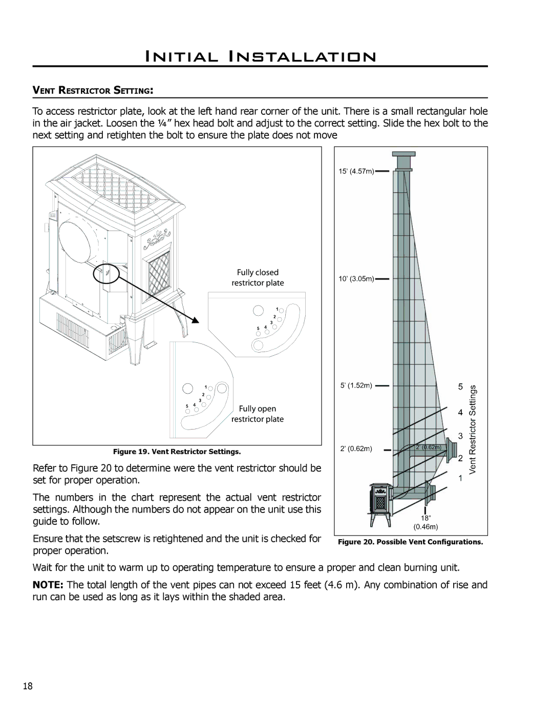
To access restrictor plate, look at the left hand rear corner of the unit. There is a small rectangular hole in the air jacket. Loosen the 1⁄4” hex head bolt and adjust to the correct setting. Slide the hex bolt to the next setting and retighten the bolt to ensure the plate does not move
|
| ����� ������ | ||
|
| ���������� ����� | ||
|
|
|
| 1 |
|
|
|
| 2 |
|
| 5 | 4 | 3 |
|
| 1 |
|
|
|
| 2 |
|
|
5 | 4 | 3 |
|
|
|
| ����� ���� | ||
|
| ���������� ����� | ||
Figure 19. Vent Restrictor Settings.
Refer to Figure 20 to determine were the vent restrictor should be set for proper operation.
The numbers in the chart represent the actual vent restrictor settings. Although the numbers do not appear on the unit use this guide to follow.
Ensure that the setscrew is retightened and the unit is checked for |
|
Figure 20. Possible Vent Configurations. | |
proper operation. |
|
Wait for the unit to warm up to operating temperature to ensure a proper and clean burning unit.
NOTE: The total length of the vent pipes can not exceed 15 feet (4.6 m). Any combination of rise and run can be used as long as it lays within the shaded area.
18
