Initial Installation
QUALIFIED INSTALLERS ONLY
FREESTANDING DRAFTHOOD ADAPTOR -
This Drafthood Adaptor is a complete assembly and is ready to fit onto your Westport in a vertical vent application only. With the Drafthood Adaptor correctly installed and wired to the gas control valve. Your Direct Vent Fireplace can be vented like a
INSTALLATION:
WARNING: This Freestanding Drafthood Adaptor must be fitted by a qualified service technician.
1.Remove the Drafthood Adaptor from the packaging. Ensure the unit and wire harness are undamaged. If there is damage contact your dealer, distributor, or courier company before starting this installation.
2.Install the adaptor so the wires exit to the rear of the fireplace. Slide the Drafthood Adaptor over the outlet pipe of the fireplace until the bottom of the adaptor collar stops on the top of the outlet. The Drafthood Adaptor must be safely secured to the vent flanges with either
WARNING: During the fitting of the Drafthood Adaptor, ensure that the wires are not pinched between the adaptor and the collar and/or flue outlet. Ensure that the opening of the Drafthood Adaptor is not blocked or obstructed.
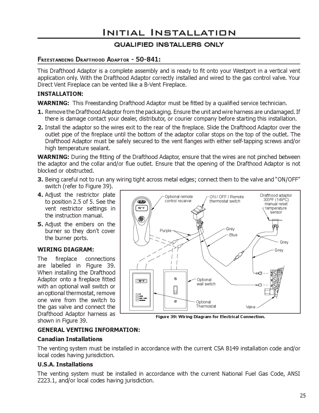
3.Being careful not to run any wiring tight across metal edges; connect them to the valve and “ON/OFF” switch (refer to Figure 39).
4. Adjust the restrictor plate | Optional remote | ON / OFF / Remote | Drafthood adaptor | |||
to position 2.5 of 5. See the | 300oF (149oC) | |||||
control receiver | thermostat switch | |||||
manual reset | ||||||
vent restrictor | settings | in |
|
| temperature | |
the instruction manual. |
|
|
| sensor | ||
|
|
|
| |||
5. Adjust the embers on | the |
| Grey |
| ||
burner so they don’t cover | Purple |
| ||||
Blue |
| |||||
the burner ports. |
|
|
| |||
|
|
| Grey | |||
|
|
|
|
| ||
WIRING DIAGRAM: |
|
|
| Grey | ||
The fireplace | connections |
|
|
| ||
are labelled in Figure 39. |
|
|
| |||
When installing the Drafthood |
|
|
| |||
Adaptor onto a fireplace fitted |
| Optional |
| |||
with an optional wall switch or |
| wall switch |
| |||
|
|
| ||||
an optional thermostat, remove |
|
|
| |||
one wire from the switch to |
| Optional |
| |||
the gas valve and connect the |
| Thermostat | Valve | |||
Drafthood Adaptor harness as | Figure 39: Wiring Diagram for Electrical Connection. | |||||
shown in Figure 39. |
| |||||
|
|
|
| |||
GENERAL VENTING INFORMATION:
Canadian Installations
The venting system must be installed in accordance with the current CSA B149 installation code and/or local codes having jurisdiction.
U.S.A. Installations
The venting system must be installed in accordance with the current National Fuel Gas Code, ANSI Z223.1, and/or local codes having jurisdiction.
25
