Manuals
/
Brands
/
Computer Equipment
/
Computer Hardware
/
EPoX Computer
/
Computer Equipment
/
Computer Hardware
EPoX Computer
EP-3VCA2
- page 71
1
71
71
Download
71 pages, 1.67 Mb
Appendix
EP-3VCA2
A-19
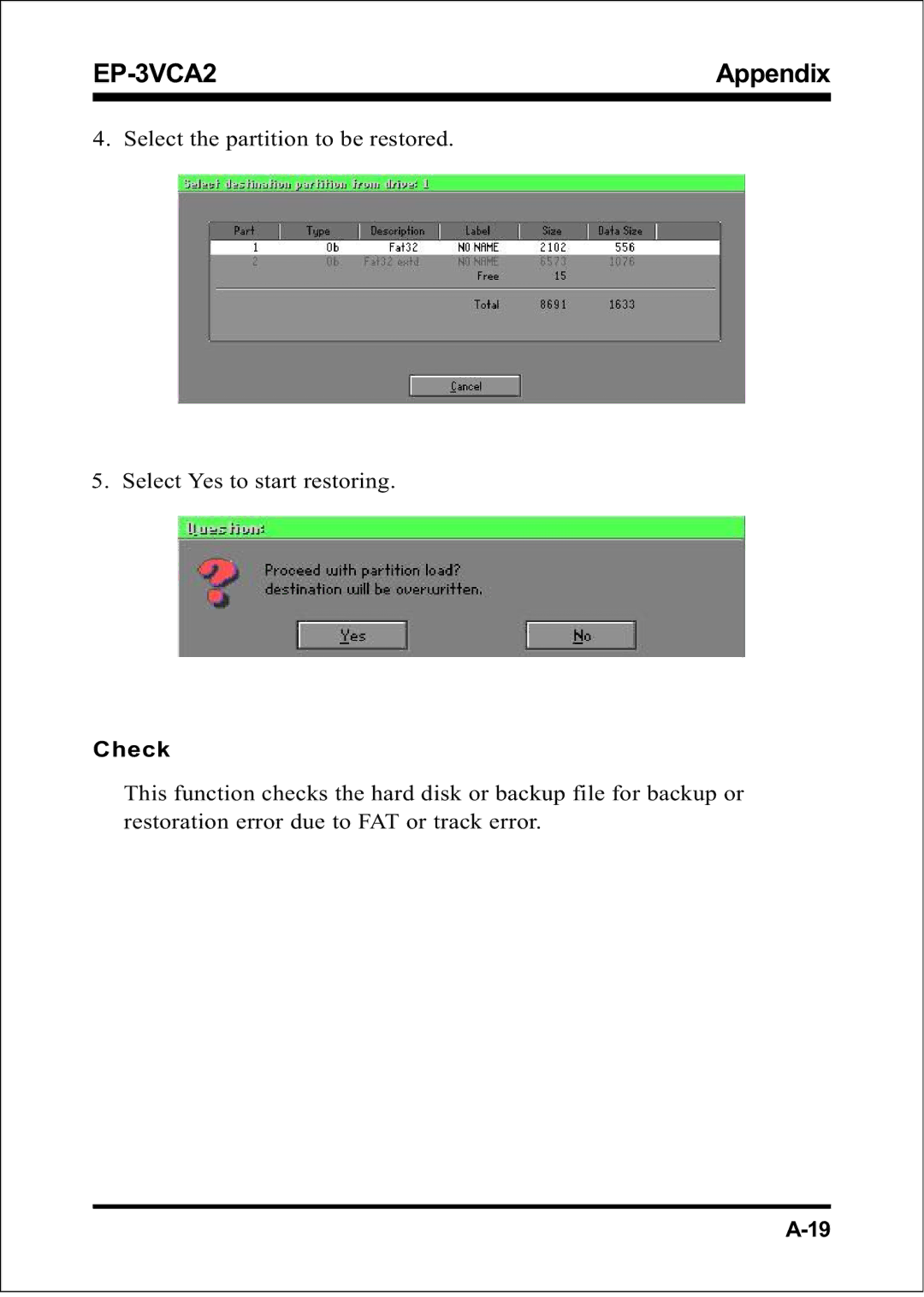
4.
Select the partition to be restored.
5.
Select Yes to start restoring.
Check
This function checks the hard disk or backup file for backup or
restoration error due to FAT or track error.
Contents
Main
EP-3VEP-3V
EP-3VEP-3V EP-3VCA2CA2
CA2CA2 CA2
EP-3VCA2 User Notice
Handling Procedures
CAUTION
EP-3VCA2 Technical Support Services
Contacting Technical Support
North American website (English language)
European website (Multi-language)
Taiwan website (Chinese language)
Table of Contents
Page
Page
IntroductionEP-3VCA2
Section 1 INTRODUCTION
Components Checklist
Introduction EP-3VCA2
EP-3VCA2 Form-Factor
5 1/4" Bay
3 1/2" Bay
IntroductionEP-3VCA2
Power-On/Off (Remote)
I/O Shield Connector
Introduction EP-3VCA2
Figure 5: System Block Diagram
Socket 370 Processor
VT82C686A I/O Bridge
FeaturesEP-3VCA2
Section 2 FEATURES
EP-3VCA2 Features:
Features EP-3VCA2
Page
Page
Easy Installation Procedure
Section 3-1 CPU Insertion
Page
Page 3-5
Section 3-2 Jumper Settings
JP1 CMOS Clear JP1 = 1-2 Normal (Default) = 2-3 Clear CMOS
SW2: CPU Vcore Voltage Selection
JP2: VIO (3.3V) Adjust Selection
2PJtsujdA)V3.3(OIV 6-1V0.0+ 7-2V50.0+ 8-3V1.0+ 9-4V51.0+ 01-5V2.0+
Page
Section 3-3 System Memory Configuration Memory Layout
DIMM Module Installation
Section 3-4 Device Connectors
Page
Device Connectors
Section 3-5 External Modem Ring-in Power ON and Keyboard Power ON Functions (KBPO)
JP4 Keyboard Power-ON Function JP4 = 1-2 Disabled (Default) = 2-3 Enabled
3-6 STR (Suspend To RAM) Function
Page
Section 4 BIOS SETUP
4-1 Standard CMOS Setup
Page
Page
Page
Page
Page
4-3 Advanced Chipset Features
Page
Page
4-4 Integrated Peripherals
Page
Page
Page
Page
4-5 Power Management Setup
Page
Page
Page
Page
4-7 PC Health Status
4-8 Frequency/Voltage Control
4-9 Defaults Menu
4-10 Supervisor/User Password Setting
ENTER PASSWORD:
PASSWORD DISABLED.
Page
Page
Appendix A
A-1 MEMORY MAP
A-2 I/O MAP
A-3 TIMER & DMA CHANNELS MAP
A-4 INTERRUPT MAP
A-5 RTC & CMOS RAM MAP
Page
Appendix B
B-1 POST CODES
Page
Page
B-2 Unexpected Errors:
Appendix C
LOAD Optimized DEFAULTS
Page
Appendix D