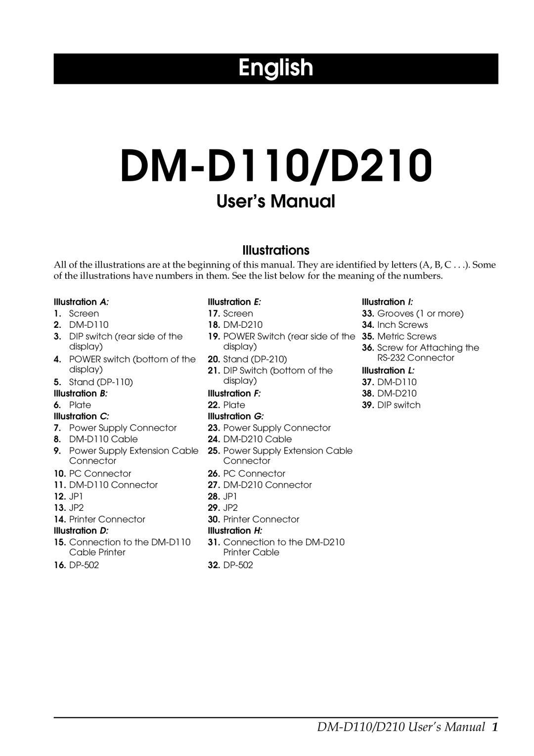
D110, D210 specifications
The Epson D110 and D210 are two prominent models in Epson's range of inkjet printers, designed to cater to both home and small office environments. Both printers exemplify high-quality printing, enhanced efficiency, and user-friendly features, making them ideal choices for those in need of reliable printing solutions.One of the standout features of the D110 and D210 models is their high-resolution printing capability. With a resolution reaching up to 4800 x 1200 optimized dpi, these printers ensure crisp, vibrant, and detailed prints. This makes them suitable for a variety of printing tasks, from documents to photos, producing professional-quality outputs that exceed the expectations of standard inkjet printers.
Both models utilize Epson’s advanced Micro Piezo technology, ensuring precision in ink placement which significantly contributes to image clarity and detail. This technology not only enhances print quality but also optimizes ink usage, thereby lowering running costs. Furthermore, the D110 and D210 are equipped with an innovative ink system, featuring individual ink cartridges. This allows users to replace only the color that runs out, thereby reducing waste and ensuring economical efficiency.
In terms of speed, the Epson D110 offers impressive print speeds up to 15 pages per minute for black-and-white documents and 8 pages per minute for color prints. The D210 improves upon this with slightly faster performance while maintaining high quality. These capabilities make both models well-suited for busy environments where time is of the essence.
Both printers are designed with user convenience in mind. They offer simple navigation through intuitive control panels and easy-to-follow instructions, making them accessible for users of all skill levels. Additionally, the D210 includes wireless printing capabilities, allowing users to print directly from their smartphones or tablets, enhancing flexibility and efficiency.
Furthermore, energy efficiency is a notable characteristic of the D110 and D210. Both models are ENERGY STAR certified, indicating that they meet strict energy efficiency guidelines, thus promoting environmentally-friendly practices while simultaneously reducing operational costs.
In conclusion, the Epson D110 and D210 printers deliver outstanding functionality, excellent print quality, and user-friendly features, making them excellent choices for both home and office use. With their advanced technologies and efficient designs, they stand out in the competitive inkjet printer market.

