| TEST PROCEDURES | TROUBLESHOOTING PROCEDURES | |
|
|
|
|
STEP 2
USABLE SENSITIVITY
(12 dB SINAD)
If STEP 1 checks out properly, measure the receiver sensitivity as follows:
A.Apply a 1000 microvolt, on frequency signal modulated by 1000 Hz with 3.0 kHz deviation to
B.With Function Switch on Distortion Analyzer set to VOLTMETER position, adjust volume control for 1.0 Watt (2.83 VRMS across 8 ohm load). Again, verify that audio output is nulled when Function Switch is set to DISTORTION position.
C.Place the RANGE switch to the SET LEVEL position (filter out of the circuit) and adjust the input LEVEL control for a +2 dB reading on a 30% range.
D.While reducing the signal generator output, switch the FUNCTION control from SET LEVEL to the DISTORTION until a 12 dB difference (+2 dB to
E.The 12 dB difference (Signal plus Noise and Distortion to noise plus distortion ratio) is the "usable" sensitivity level. The sensitivity should be less than rated 12 dB SINAD specifications with an audio output of watt across the 8.0 ohm load.
F.Leave all controls as they are and all equipment connected if the Modulation Acceptance Bandwidth test is to be performed.
SERVICE CHECK
If the sensitivity level is more than the rated 12 dB SINAD specification, check the alignment of the RF stages as directed in the Alignment Procedure, and make the gain measurements as shown on the Troubleshooting Procedure.
STEP 3
MODULATION ACCEPTANCE
BANDWIDTH (IF BANDWIDTH)
If STEPS 1 and 2 check out properly, measure the bandwidth as follows:
A.Set the Signal Generator output for twice the microvolt reading obtained in the 12- dB SINAD measurement.
B.Set the RANGE control on the Distortion Analyzer in the SET LEVEL position
C.While increasing the deviation of the Signal Generator, switch the RANGE control from SET LEVEL to distortion range until a 12- dB difference is obtained between the SET LEVEL and distortion range readings (from +2 dB to
D.The deviation control reading for the 12- dB difference is the Modulation Acceptance Bandwidth of the receiver. It should be more than ±7 kHz.
SERVICE CHECK
If the Modulation Acceptance Bandwidth test does not indicate the proper width, make gain measurements as shown on the Receiver Troubleshooting Procedure.
STEP 1 - QUICK CHECKS
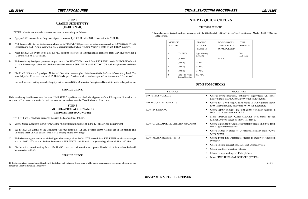
TEST SET CHECKS
These checks are typical readings measured with Test Set Model 4EX3A11 in the Test 1 position, or Model 4EX8K12 in the
METERING | READING | READING WITH- | TEST | |
POSITION | WITH NO | 10 MICROVOLTS | POSITION | |
|
| SIGNAL IN | (UNMODULATED) |
|
|
|
|
|
|
|
|
|
|
|
A | (FM DET) | Approximately |
| Test 1 |
|
| 0.38 VDC |
| (or 1 Volt) |
B | (IF Amp) |
| 0.1 VDC |
|
|
|
|
|
|
C | 0.4 VDC |
|
| |
|
|
|
|
|
D | 0.4 VDC |
|
| |
|
|
|
|
|
F | 0.1 VDC |
|
| |
|
|
|
|
|
J | (Reg. +10 Volt at | +10 VDC |
|
|
| System Metering |
|
|
|
SYMPTOM CHECKS
SYMPTOM |
| PROCEDURE |
|
|
|
NO SUPPLY VOLTAGE | ∙ | Check power connections, continuity of supply leads. Check fuse |
|
| and replace if blown. Check receiver for short circuits. |
|
|
|
NO REGULATED | ∙ | Check the 12 Volt supply. Then check 10 Volt regulator circuit. |
|
| (See Troubleshooting Procedure for 10 Volt Regulator). |
|
|
|
LOW IF READING | ∙ | Check supply voltages and then check oscillator readings at |
|
| |
| ∙ | Make SIMPLIFIED GAIN CHECKS from Mixer through |
|
| Limiter Detector stages as shown in STEP 2. |
|
|
|
LOW OSCILLATOR/MULTIPLIER READINGS | ∙ | Check alignment of Oscillator/Multiplier chain. (Refer to Front |
|
| End Alignment Procedure). |
| ∙ Check voltage readings of Oscillator/Multiplier chain (Q401, | |
|
| Q402, Q403). |
|
|
|
LOW RECEIVER SENSITIVITY | ∙ | Check Front End Alignment. (Refer to Receiver Alignment |
|
| Procedure). |
| ∙ Check antenna connections, cable and antenna switch. | |
| ∙ Check Oscillator injection voltage. | |
| ∙ Check voltage readings of IF Amplifiers. | |
| ∙ Make SIMPLIFIED GAIN CHECKS (STEP 2). | |
|
|
|
|
| Con’t. |
8