| TEST PROCEDURES | |
|
|
|
TEST PROCEDURES
These Test Procedures are designed to help you to service a receiver that is
TEST EQUIPMENT REQUIRED
∙Distortion Analyzer similar to:
HP331A, or an equivalent average response meter
∙Signal Generator similar to: HP8640B
∙
Once the defective stage is
PRELIMINARY ADJUSTMENTS
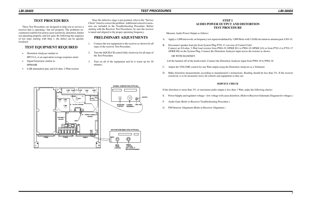
1.Connect the test equipment to the receiver as shown for all steps of the receiver Test Procedure.
2.Turn the SQUELCH control fully clockwise for all steps of the Test Procedure.
3.Turn on all of the equipment and let it warm up for 20 minutes.
STEP 1
AUDIO POWER OUTPUT AND DISTORTION
TEST PROCEDURE
Measure Audio Power Output as follows:
A.Apply a 1,000 microvolt, on frequency test signal modulated by 1,000 Hertz with 3.0 kHz deviation to antenna jack
B.Disconnect speaker lead pin from System Plug
Connect an
OR WITH HANDSET:
Lift the handset off of the hookswitch. Connect the Distortion Analyzer input from
C.Adjust the VOLUME control for one Watt output using the Distortion Analyzer as a Voltmeter.
D.Make distortion measurements according to manufacturer’s instructions. Reading should be less than 3%. If the receiver sensitivity is to be measured, leave all controls and equipment as they are.
SERVICE CHECK
If the distortion is more than 3%, or maximum audio output is less than 1 Watt, make the following checks:
E.Power Supply and regulator
F.Audio Gain (Refer to Receiver Troubleshooting Procedure.)
G.FM Detector Alignment (Refer to Receiver Alignment.)
7