LBI-39101

INTERCONNECTING THE EQUIPMENT

assembled with one amplified speaker in the far left-hand position (select speaker), one amplified speaker in the far right-hand position (unselect speaker) and blank panels installed in the two center positions. Four-speaker consoles are generally equipped with two separate 2-speaker rack mountG￿assemblies.

Install or mount each Speaker Assembly in a suitable location and then interconnect it to the

Enhanced Audio Enclosure using cable P29/5010150000 (350A1371P29). This cable is 9 feet (2.74 meters) in length. It is identical to the cable that interconnects the PC's serial COM port to the Enhanced Audio Enclosure. Mate the cable's female DB-9 connector to the appropriate male DB-9 connector on the Enhanced Audio Enclosure's rear panel. These male connectors are labeled "SEL SPKR" (select speaker), "UNSEL SPKR1" (first unselect speaker), "UNSEL SPKR2" (second unselect speaker) and "UNSEL SPKR3" (third unselect speaker). Connect the other end of the cable to the female DB-9 connector at the respective Speaker Assembly. If necessary, see Tables 18 and 19 for DB-9 pin-outs.

NOTE

Load resistors are not required for unused Enhanced Audio Enclosure speaker outputs.

Recorder Outputs (if used)

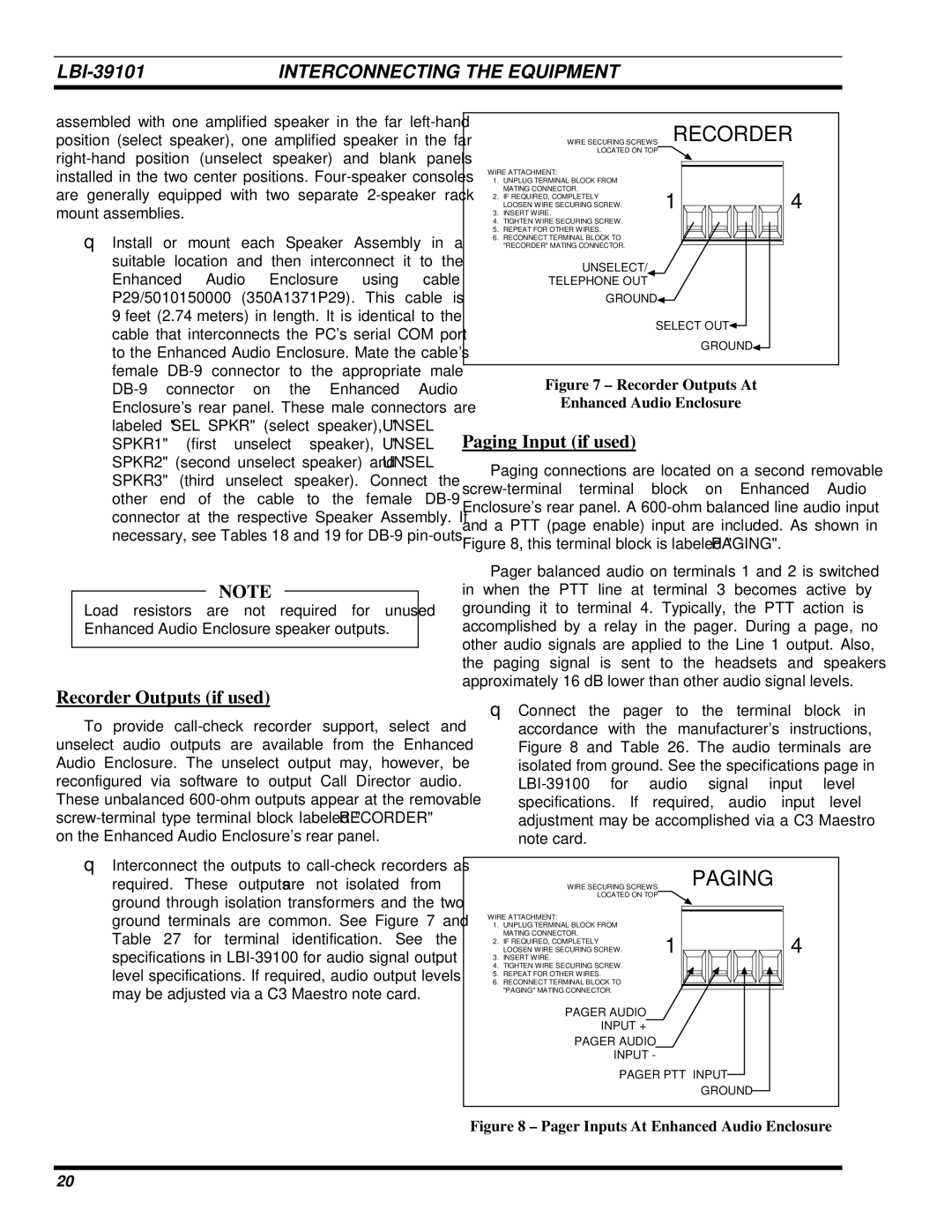
To provide call-check recorder support, select and unselect audio outputs are available from the Enhanced Audio Enclosure. The unselect output may, however, be reconfigured via software to output Call Director audio. These unbalanced 600-ohm outputs appear at the removable screw-terminal type terminal block labeled "RECORDER" on theG￿Enhanced Audio Enclosure's rear panel.

Interconnect the outputs to call-check recorders as required. These outputs are not isolated from ground through isolation transformers and the two ground terminals are common. See Figure 7 and Table 27 for terminal identification. See the specifications in LBI-39100 for audio signal output level specifications. If required, audio output levels may be adjusted via a C3 Maestro note card.


WIRE SECURING SCREWS

RECORDER


LOCATED ON TOP


WIRE ATTACHMENT:


1.

UNPLUG TERMINAL BLOCK FROM


MATING CONNECTOR.

1

4

2.

IF REQUIRED, COMPLETELY


LOOSEN WIRE SECURING SCREW.

3.

INSERT WIRE.


4.

TIGHTEN WIRE SECURING SCREW.


5.

REPEAT FOR OTHER WIRES.


6.

RECONNECT TERMINAL BLOCK TO


"RECORDER" MATING CONNECTOR.


UNSELECT/

TELEPHONE OUT

GROUND

SELECT OUT

GROUND

Figure 7 – Recorder Outputs At

Enhanced Audio Enclosure

Paging Input (if used)

Paging connections are located on a second removable screw-terminal terminal block on Enhanced Audio Enclosure's rear panel. A 600-ohm balanced line audio input and a PTT (page enable) input are included. As shown in Figure 8, this terminal block is labeled "PAGING".

Pager balanced audio on terminals 1 and 2 is switched in when the PTT line at terminal 3 becomes active by grounding it to terminal 4. Typically, the PTT action is accomplished by a relay in the pager. During a page, no other audio signals are applied to the Line 1 output. Also, the paging signal is sent to the headsets and speakers approximatelyG￿16 dB lower than other audio signal levels.

Connect the pager to the terminal block in accordance with the manufacturer's instructions, Figure 8 and Table 26. The audio terminals are isolated from ground. See the specifications page in LBI-39100 for audio signal input level specifications. If required, audio input level adjustment may be accomplished via a C3 Maestro note card.


WIRE SECURING SCREWS


PAGING


LOCATED ON TOP


WIRE ATTACHMENT:


1.

UNPLUG TERMINAL BLOCK FROM


MATING CONNECTOR.

1

4

2.

IF REQUIRED, COMPLETELY


LOOSEN WIRE SECURING SCREW.

3.

INSERT WIRE.


4.

TIGHTEN WIRE SECURING SCREW.


5.

REPEAT FOR OTHER WIRES.


6.

RECONNECT TERMINAL BLOCK TO


"PAGING" MATING CONNECTOR.


PAGER AUDIO

INPUT +

PAGER AUDIO

INPUT -

PAGER PTT INPUT

GROUND

Figure 8 – Pager Inputs At Enhanced Audio Enclosure

20

Page 20
Image 20
Ericsson LBI-39101A manual Recorder Outputs if used, Paging Input if used

LBI-39101A specifications

The Ericsson LBI-39101A is a robust and versatile base station designed to facilitate efficient communication networks. Known for its reliable performance, the LBI-39101A plays a crucial role in enhancing the connectivity landscape for mobile operators. This equipment supports a range of technologies, making it an ideal choice for operators aiming to deliver high-quality services in both urban and rural environments.

One of the key features of the LBI-39101A is its support for multiple frequency bands, allowing it to operate across various spectrum allocations. This flexibility enables mobile operators to effectively manage their frequency resources and optimize network performance. Additionally, the base station is designed to support both 2G and 3G technologies, making it a valuable asset for operators transitioning to newer standards while still catering to older devices in their network.

The LBI-39101A also incorporates advanced receiver and transmitter technology, which enhances its ability to handle high traffic loads and support a larger number of simultaneous users. This capability is crucial in densely populated areas where network demand is high. The base station's design also emphasizes energy efficiency, reducing both operational costs and environmental impact, which is becoming increasingly important in today's eco-conscious world.

Another notable characteristic of the LBI-39101A is its modular architecture. This design allows for easy upgrades and scalability, enabling operators to expand their network capabilities without the need for extensive infrastructure overhauls. The base station can accommodate future enhancements seamlessly, ensuring that it remains competitive as technology evolves.

Moreover, the LBI-39101A includes built-in support for advanced features such as MIMO (Multiple Input Multiple Output) technology, which improves data throughput and reliability. This is particularly significant as mobile data consumption continues to rise, placing immense pressure on existing networks. The MIMO capability allows for enhanced spectral efficiency, which is crucial for maximizing the available bandwidth.

In summary, the Ericsson LBI-39101A stands out as a powerful base station with a host of features designed for modern mobile communication. Its support for multiple technologies, energy efficiency, modular design, and advanced MIMO capabilities make it an excellent choice for operators looking to enhance their networks and provide superior connectivity for users. As the mobile landscape evolves, the LBI-39101A is poised to remain a key player in facilitating seamless communication.