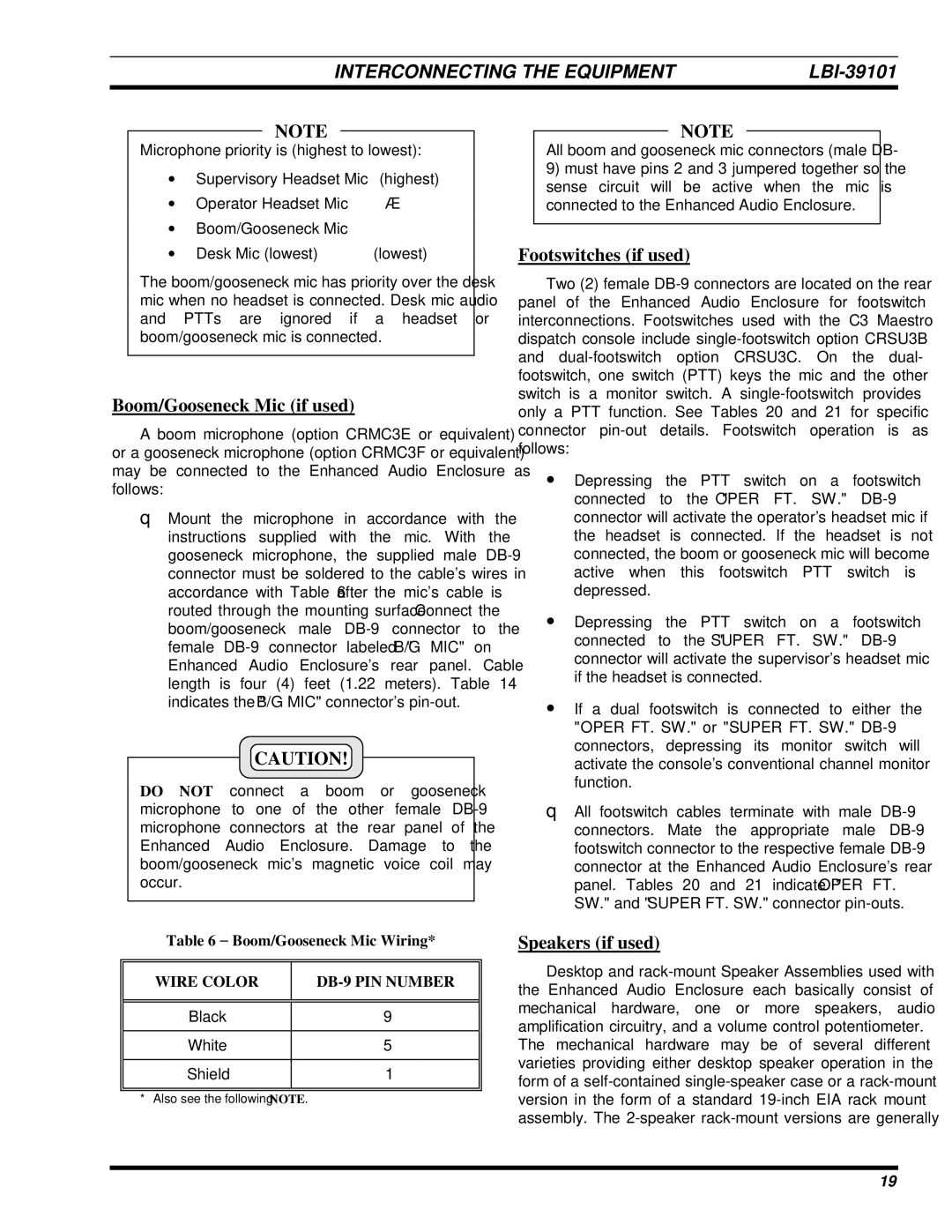
LBI-39101A specifications
The Ericsson LBI-39101A is a robust and versatile base station designed to facilitate efficient communication networks. Known for its reliable performance, the LBI-39101A plays a crucial role in enhancing the connectivity landscape for mobile operators. This equipment supports a range of technologies, making it an ideal choice for operators aiming to deliver high-quality services in both urban and rural environments.One of the key features of the LBI-39101A is its support for multiple frequency bands, allowing it to operate across various spectrum allocations. This flexibility enables mobile operators to effectively manage their frequency resources and optimize network performance. Additionally, the base station is designed to support both 2G and 3G technologies, making it a valuable asset for operators transitioning to newer standards while still catering to older devices in their network.
The LBI-39101A also incorporates advanced receiver and transmitter technology, which enhances its ability to handle high traffic loads and support a larger number of simultaneous users. This capability is crucial in densely populated areas where network demand is high. The base station's design also emphasizes energy efficiency, reducing both operational costs and environmental impact, which is becoming increasingly important in today's eco-conscious world.
Another notable characteristic of the LBI-39101A is its modular architecture. This design allows for easy upgrades and scalability, enabling operators to expand their network capabilities without the need for extensive infrastructure overhauls. The base station can accommodate future enhancements seamlessly, ensuring that it remains competitive as technology evolves.
Moreover, the LBI-39101A includes built-in support for advanced features such as MIMO (Multiple Input Multiple Output) technology, which improves data throughput and reliability. This is particularly significant as mobile data consumption continues to rise, placing immense pressure on existing networks. The MIMO capability allows for enhanced spectral efficiency, which is crucial for maximizing the available bandwidth.
In summary, the Ericsson LBI-39101A stands out as a powerful base station with a host of features designed for modern mobile communication. Its support for multiple technologies, energy efficiency, modular design, and advanced MIMO capabilities make it an excellent choice for operators looking to enhance their networks and provide superior connectivity for users. As the mobile landscape evolves, the LBI-39101A is poised to remain a key player in facilitating seamless communication.

