Electrical Control Module 20A Power Conditioner
4 |
|
|
| 6 | |
|
|
|
| ||
|
|
|
|
| |
1
3
2
MODULE PANEL FEATURES
1.Trigger / Status Port Pin Identification – All signals are of low voltage and current. DO NOT MISWIRE or damage may occur.
+Requires 5
The EVS protection requires the
G Circuit Ground, Must be of the same circuit as the DCV source.
VAC Voltage Status Signal, this signal reports back to the
AAC Current Status Signal, this signal reports back to the
DFault Status Signal, reports to the
2.External Trigger / Manual On Switch – The
3.Incoming AC LED – This LED will illuminate Red when the ECM has incoming AC power present at the module. This LED must be On to operate. Note: If this LED is not illuminating check the following: 1) The unit is plugged in, 2) The AC Mains
Breaker feeding the AC leg to the ECM module is OFF, 3) The internal fuse has been damaged. This should only be inspected by an authorized technician.
4.Active LED – This LED will illuminate Green when the ECM module has sensed the proper DCV to trigger activate the power on circuit. Note: If connected to the
AC Mains voltage is stable.
5.AC Fault LED – If damage to the Spike Suppression circuit occurred this LED will illuminate Red. The module may still operate but may not be protecting the items plugged into the AC outlets. This LED will not turn off until repaired. Have the ECM module inspected by a qualified technician.
Note: Not available on
6.AC Mains Outlet – Two 120V AC 20A outlets.
4 |
|
|
| 6 | |
|
|
|
| ||
|
|
|
|
| |
1 |
|
3 |
|
5 | 2 |
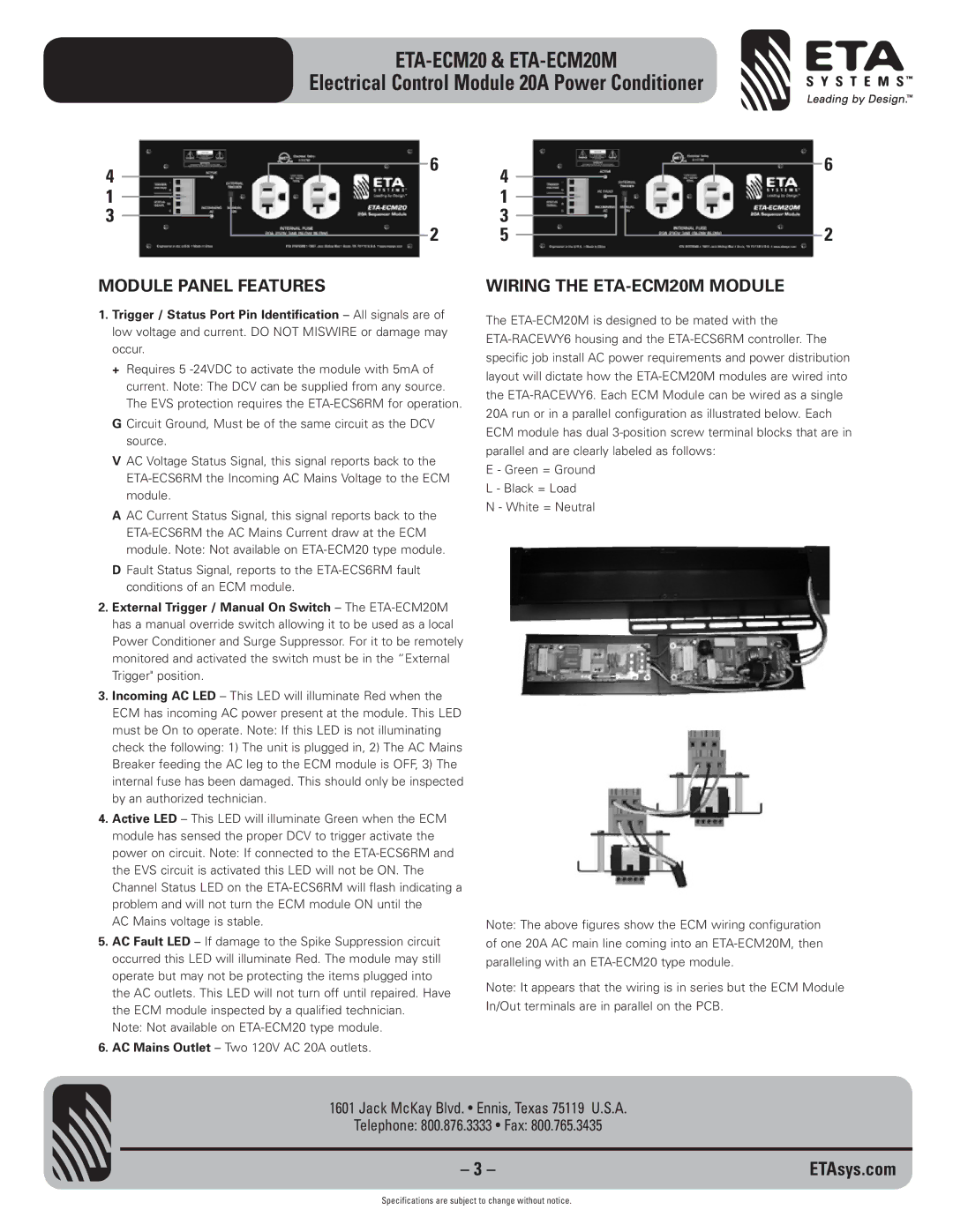
WIRING THE ETA-ECM20M MODULE
The
E - Green = Ground L - Black = Load N - White = Neutral
Note: The above figures show the ECM wiring configuration of one 20A AC main line coming into an
Note: It appears that the wiring is in series but the ECM Module In/Out terminals are in parallel on the PCB.
1601 Jack McKay Blvd. • Ennis, Texas 75119 U.S.A.
Telephone: 800.876.3333 • Fax: 800.765.3435
– 3 – | ETAsys.com |
Specifications are subject to change without notice.