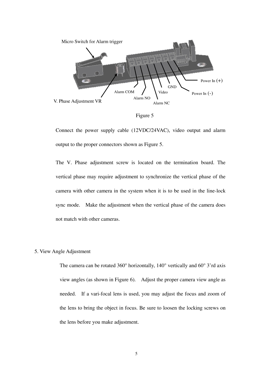
Micro Switch for Alarm trigger
|
|
| Power In (+) |
| Alarm COM | GND |
|
| Video | Power In | |
V. Phase Adjustment VR | Alarm NO | Alarm NC |
|
|
| ||
|
|
|
Figure 5
Connect the power supply cable (12VDC/24VAC), video output and alarm output to the proper connectors shown as Figure 5.
The V. Phase adjustment screw is located on the termination board. The vertical phase may require adjustment to synchronize the vertical phase of the camera with other camera in the system when it is to be used in the
5. View Angle Adjustment
The camera can be rotated 360° horizontally, 140° vertically and 60° 3’rd axis view angles (as shown in Figure 6). Adjust the proper camera view angle as needed. If a
5