C H A P T E R 2 I N S T A L L A T I O N
C H A P T E R 1 P R O D U C T O V E R V I E W
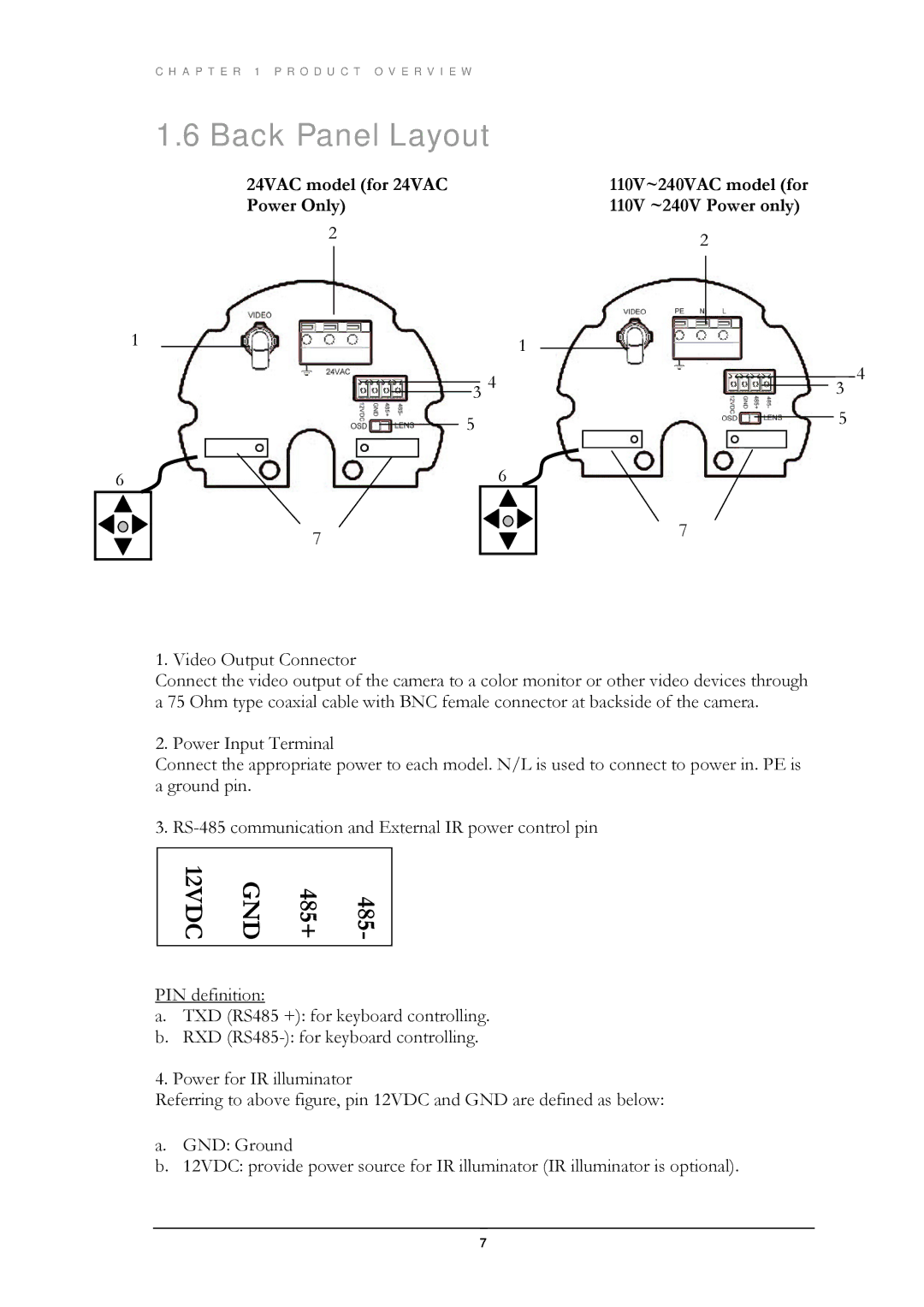
1.6 Back Panel Layout
24VAC model (for 24VAC Power Only)
2
1 |
| 1 |
|
3 4 |
110V~240VAC model (for 110V ~240V Power only)
2
3
4
| 5 |
6 | 6 |
| 7 |
5
7
1. Video Output Connector
Connect the video output of the camera to a color monitor or other video devices through a 75 Ohm type coaxial cable with BNC female connector at backside of the camera.
2. Power Input Terminal
Connect the appropriate power to each model. N/L is used to connect to power in. PE is a ground pin.
3.
12VDC | GND | 485+ | 485- |
|
|
|
|
PIN definition:
a.TXD (RS485 +): for keyboard controlling.
b.RXD
4. Power for IR illuminator
Referring to above figure, pin 12VDC and GND are defined as below:
a.GND: Ground
b.12VDC: provide power source for IR illuminator (IR illuminator is optional).
7