Hardware Installation
USB Headers
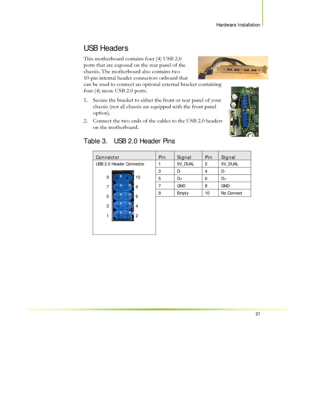
This motherboard contains four (4) USB 2.0 ports that are exposed on the rear panel of the chassis. The motherboard also contains two
can be used to connect an optional external bracket containing four (4) more USB 2.0 ports.
1.Secure the bracket to either the front or rear panel of your chassis (not all chassis are equipped with the front panel option).
2.Connect the two ends of the cables to the USB 2.0 headers on the motherboard.
Table 3. USB 2.0 Header Pins
Connector |
|
| Pin |
|
USB 2.0 Header Connector | 1 |
| ||
|
|
|
|
|
|
|
| 3 |
|
9 | 10 |
|
|
|
| 5 |
| ||
|
|
|
| |
|
|
|
|
|
7 | 8 |
| 7 |
|
5 | 6 |
| 9 |
|
|
|
| ||
|
|
| ||
3 | 4 |
|
|
|
1 | 2 |
|
|
|
|
|
|
|
|
Signal
5V_DUAL D-
D+
GND
Empty
Pin | Signal |
2 | 5V_DUAL |
|
|
4 | D- |
|
|
6 | D+ |
|
|
8 | GND |
|
|
10 | No Connect |
|
|
21