Manuals
/
Exmark
/
Lawn and Garden
/
Lawn Mower
Exmark
4500-352
manual
Adjusting the Number of Spacers below Caster Support Hub, Maintenance
Models:
4500-352
1
27
40
40
Download
40 pages
18.13 Kb
24
25
26
27
28
29
30
31
Troubleshooting
Specification
Schematics
Safety Alert Symbol
Warranty
Dimension
Maintenance
Adjustments
Cleaning
Safety
Page 27
Image 27
Page 26
Page 28
Page 27
Image 27
Page 26
Page 28
Contents
For Serial Nos 790,000 & Higher
METRO
CALIFORNIA Proposition 65 Warning
Model No Serial No
Introduction
Contents
ALERT! YOUR SAFETY IS INVOLVED
Safety
Safety Alert Symbol
Safety
Keep away from eyes and skin Never siphon by mouth
DANGER
Avoid prolonged breathing of vapors
Keep face away from nozzle and gas tank/container opening
Remove accumulated debris from muffler and engine area
Operation
Slope Operation
Allow engine parts, especially the muffler, to cool before touching
Do Not mow near drop-offs or near water
Maintenance and Storage
Do Not mow slopes when grass is wet
Mow across slopes, never up and down
Safety and Instructional Decals
ECS Units Only
Pistol Grip Units Only
48 inch Units Only
Model Numbers
Specifications
Specifications
Safety Interlock System
Cutting Deck
Dimensions
Curb Weight
Torque Requirements
Operation
Product Overview
Operation
Controls
Choke Control
“Off-Run” Switch
Drive Levers
Neutral Lock/Park Brake Latches
Starting the Engine
Pre-Start
Operating Instructions
Open the Fuel Shut-Off Valve
For ECS Handles
Driving the Machine
Drive Lever/Neutral Lock/Park Brake Latch Operation
For Pistol Grip Handles
Transporting a Unit
If necessary, use assistance when loading
Transporting
Changing Gears
Maintenance
Recommended Maintenance Schedules
Maintenance
Check Engine Oil Level
Periodic Maintenance
Service Interval Before each use or daily
Service Interval As required
Service Interval After the first 5 hours
Check Safety Interlock System
Service Pre-Cleaner Element and Air Cleaner
SERVICE DEALER
Check Condition Of Belts
Service Interval Every 40 hours
Note See chart for service intervals
Check Tire Pressures
Yearly-Replace gearbox grease
Service Interval Every 160 hours
Check Spark Plugs
Change Fuel Filter
Mobil HTS Grease Or Food-Grade Anti-seize
Adjustments
Adjusting the Cutting Height
Thread Locking Adhesives
Height
Cutting
Axle
Number Of Spacers
Adjusting the Axle Position
3. Place the drive levers in the “park brake” position
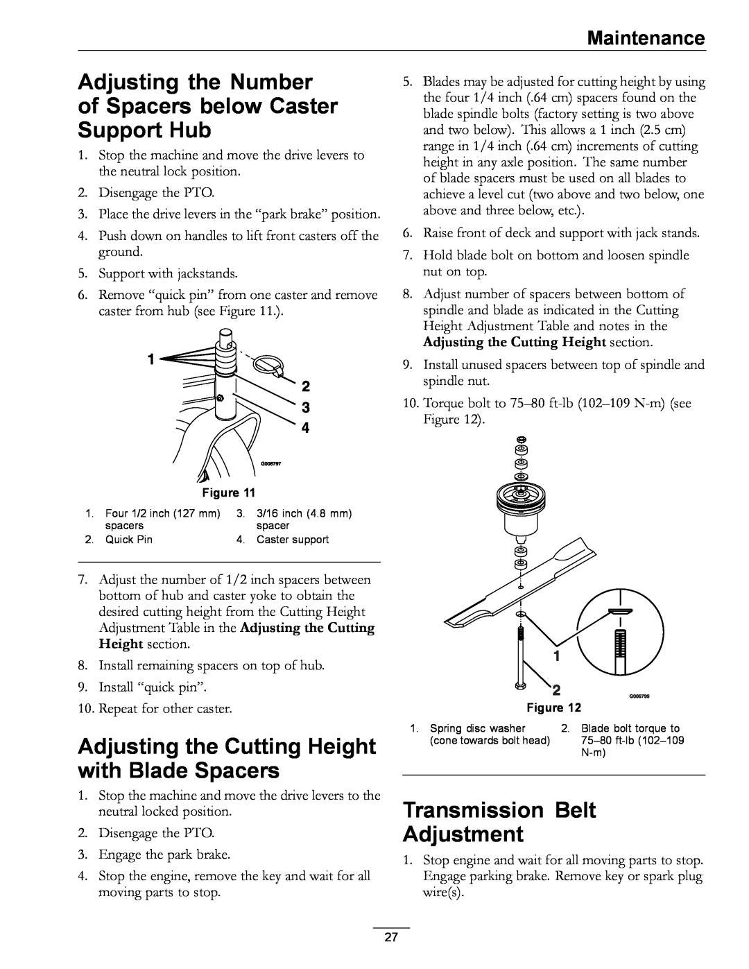
Adjusting the Number of Spacers below Caster Support Hub
Adjusting the Cutting Height with Blade Spacers
Transmission Belt Adjustment
Wheel Drive Belt Pulley Scrapers
Engine to Mower Deck Belt
48 inch Deck Shown for Reference Only
Belt Guide Adjustment
Blade Brake Adjustment
Brake and Wheel Drive Linkage Adjustment
Right Side of Unit Shown
Shifter Lever Adjustment
Shifter Detent Adjustment
PTO Safety Switch Adjustment
Handle Height Adjustment
More traction applied as
Wheel Drive Spring Tension Adjustment
Upper Handle
Upper Hole
Remove Engine Shrouds and Clean Cooling Fins
Cleaning
Clean Engine and Exhaust System Area
Clean Debris From Machine
Troubleshooting
Troubleshooting
Cutting blades is/are bent or unbalanced
Schematics
Schematics
Owner’s Responsibilities
Exmark Commercial Turf Equipment
2 Year Limited Warranty
Instructions for Obtaining Warranty Service
Page
WALK-BEHIND ACCESSORIES AND OPTIONS
SEE EXMARK’S COMPLETE LINE OF ACCESSORIES AND OPTIONS
MID-MOUNT RIDING ACCESSORIES AND OPTIONS
OUT-FRONT RIDING ACCESSORIES AND OPTIONS
Top
Page
Image
Contents