Maintenance
Figure 12
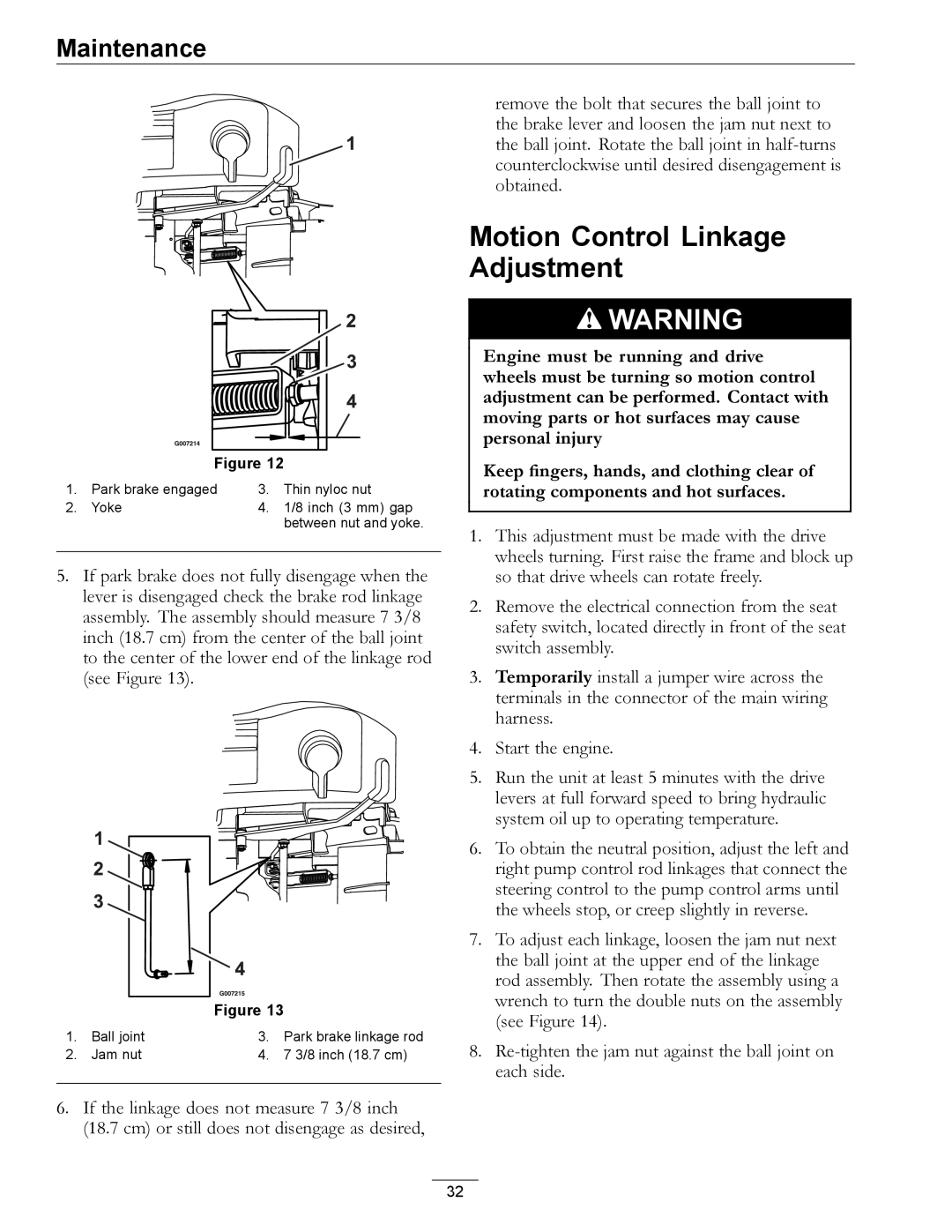
1. | Park brake engaged | 3. | Thin nyloc nut |
2. | Yoke | 4. | 1/8 inch (3 mm) gap |
|
|
| between nut and yoke. |
5.If park brake does not fully disengage when the lever is disengaged check the brake rod linkage assembly. The assembly should measure 7 3/8 inch (18.7 cm) from the center of the ball joint to the center of the lower end of the linkage rod (see Figure 13).
Figure 13
1. | Ball joint | 3. | Park brake linkage rod |
2. | Jam nut | 4. | 7 3/8 inch (18.7 cm) |
6.If the linkage does not measure 7 3/8 inch (18.7 cm) or still does not disengage as desired,
remove the bolt that secures the ball joint to the brake lever and loosen the jam nut next to the ball joint. Rotate the ball joint in
Motion Control Linkage Adjustment
![]() WARNING
WARNING
Engine must be running and drive wheels must be turning so motion control adjustment can be performed. Contact with moving parts or hot surfaces may cause personal injury
Keep fingers, hands, and clothing clear of rotating components and hot surfaces.
1.This adjustment must be made with the drive wheels turning. First raise the frame and block up so that drive wheels can rotate freely.
2.Remove the electrical connection from the seat safety switch, located directly in front of the seat switch assembly.
3.Temporarily install a jumper wire across the terminals in the connector of the main wiring harness.
4.Start the engine.
5.Run the unit at least 5 minutes with the drive levers at full forward speed to bring hydraulic system oil up to operating temperature.
6.To obtain the neutral position, adjust the left and right pump control rod linkages that connect the steering control to the pump control arms until the wheels stop, or creep slightly in reverse.
7.To adjust each linkage, loosen the jam nut next the ball joint at the upper end of the linkage rod assembly. Then rotate the assembly using a wrench to turn the double nuts on the assembly (see Figure 14).
8.
32