FIG. 8
THIS CLEARANCE SHOULD BE EQUAL
FIG. 7
SHIFTER LEVER
TO TRANSMISSION
FIG. 9
THIS CLEARANCE SHOULD BE EQUAL
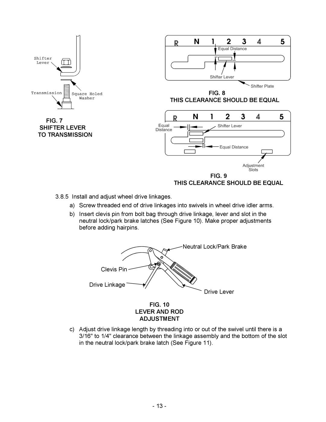
3.8.5Install and adjust wheel drive linkages.
a)Screw threaded end of drive linkages into swivels in wheel drive idler arms.
b)Insert clevis pin from bolt bag through drive linkage, lever and slot in the neutral lock/park brake latches (See Figure 10). Make proper adjustments before adding hairpins.
![]() Neutral Lock/Park Brake
Neutral Lock/Park Brake
Clevis Pin ![]()
![]()
![]()
![]()
![]()
![]()
![]()
![]()
![]()
![]()
![]()
![]()
Drive Linkage ![]()
Drive Lever
FIG. 10
LEVER AND ROD
ADJUSTMENT
c)Adjust drive linkage length by threading into or out of the swivel until there is a 3/16" to 1/4" clearance between the linkage assembly and the bottom of the slot in the neutral lock/park brake latch (See Figure 11).
- 13 -