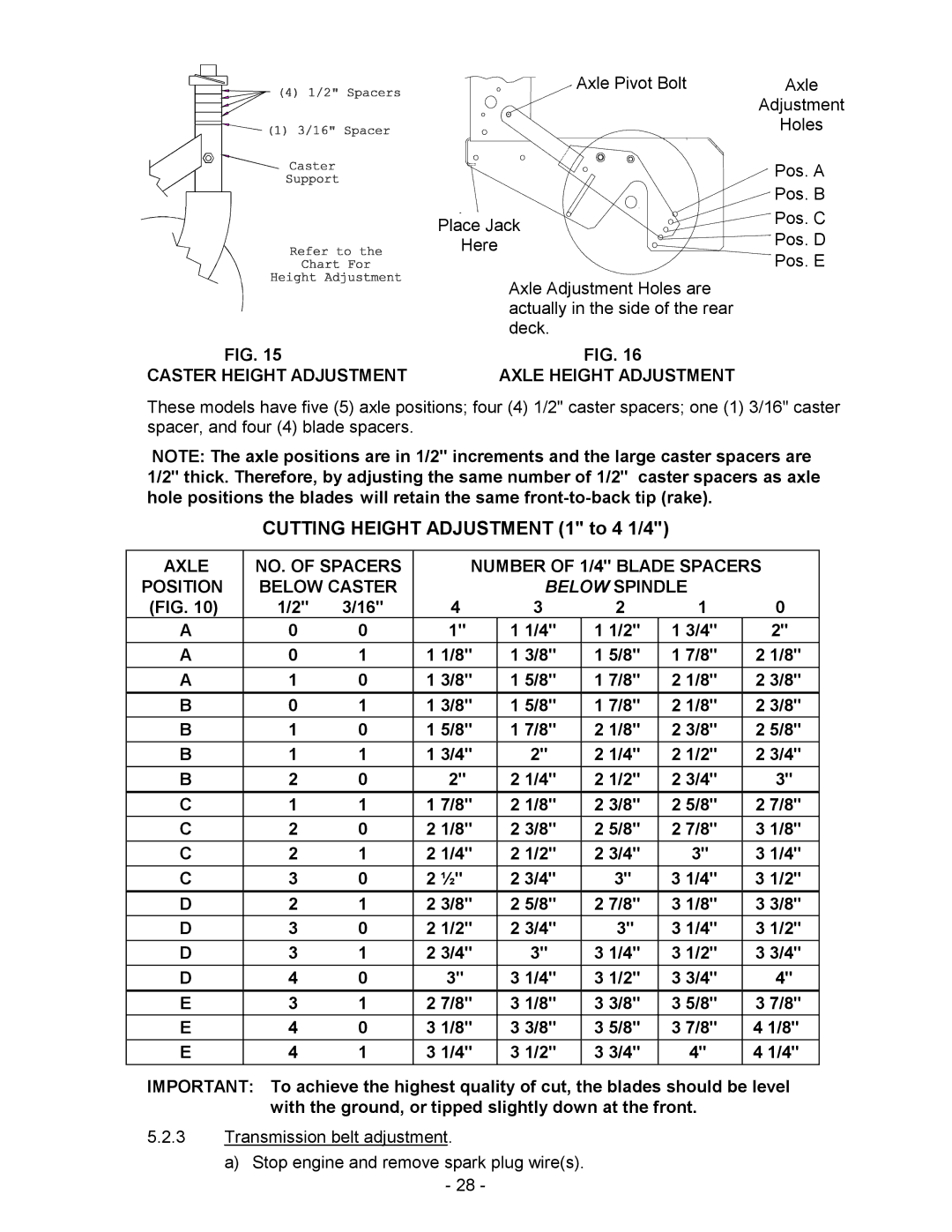
Axle Pivot Bolt
| Place Jack |
| Here |
| Axle Adjustment Holes are |
| actually in the side of the rear |
| deck. |
FIG. 15 | FIG. 16 |
CASTER HEIGHT ADJUSTMENT | AXLE HEIGHT ADJUSTMENT |
Axle
Adjustment
Holes
Pos. A
Pos. B
Pos. C
Pos. D
Pos. E
These models have five (5) axle positions; four (4) 1/2" caster spacers; one (1) 3/16" caster spacer, and four (4) blade spacers.
NOTE: The axle positions are in 1/2" increments and the large caster spacers are 1/2" thick. Therefore, by adjusting the same number of 1/2" caster spacers as axle hole positions the blades will retain the same
CUTTING HEIGHT ADJUSTMENT (1" to 4 1/4")
AXLE | NO. OF SPACERS |
| NUMBER OF 1/4" BLADE SPACERS | |||||
POSITION | BELOW CASTER |
|
| BELOW SPINDLE |
| |||
(FIG. 10) | 1/2" | 3/16" |
| 4 | 3 | 2 | 1 | 0 |
A | 0 | 0 |
| 1" | 1 1/4" | 1 1/2" | 1 3/4" | 2" |
A | 0 | 1 | 1 | 1/8" | 1 3/8" | 1 5/8" | 1 7/8" | 2 1/8" |
A | 1 | 0 | 1 | 3/8" | 1 5/8" | 1 7/8" | 2 1/8" | 2 3/8" |
B | 0 | 1 | 1 | 3/8" | 1 5/8" | 1 7/8" | 2 1/8" | 2 3/8" |
B | 1 | 0 | 1 | 5/8" | 1 7/8" | 2 1/8" | 2 3/8" | 2 5/8" |
B | 1 | 1 | 1 | 3/4" | 2" | 2 1/4" | 2 1/2" | 2 3/4" |
B | 2 | 0 |
| 2" | 2 1/4" | 2 1/2" | 2 3/4" | 3" |
C | 1 | 1 | 1 | 7/8" | 2 1/8" | 2 3/8" | 2 5/8" | 2 7/8" |
C | 2 | 0 | 2 | 1/8" | 2 3/8" | 2 5/8" | 2 7/8" | 3 1/8" |
C | 2 | 1 | 2 | 1/4" | 2 1/2" | 2 3/4" | 3" | 3 1/4" |
C | 3 | 0 | 2 | ½" | 2 3/4" | 3" | 3 1/4" | 3 1/2" |
D | 2 | 1 | 2 | 3/8" | 2 5/8" | 2 7/8" | 3 1/8" | 3 3/8" |
D | 3 | 0 | 2 | 1/2" | 2 3/4" | 3" | 3 1/4" | 3 1/2" |
D | 3 | 1 | 2 | 3/4" | 3" | 3 1/4" | 3 1/2" | 3 3/4" |
D | 4 | 0 |
| 3" | 3 1/4" | 3 1/2" | 3 3/4" | 4" |
E | 3 | 1 | 2 | 7/8" | 3 1/8" | 3 3/8" | 3 5/8" | 3 7/8" |
E | 4 | 0 | 3 | 1/8" | 3 3/8" | 3 5/8" | 3 7/8" | 4 1/8" |
E | 4 | 1 | 3 | 1/4" | 3 1/2" | 3 3/4" | 4" | 4 1/4" |
IMPORTANT: To achieve the highest quality of cut, the blades should be level with the ground, or tipped slightly down at the front.
5.2.3Transmission belt adjustment.
a)Stop engine and remove spark plug wire(s).
-28 -
