![]() 3/16” TO 1/4”
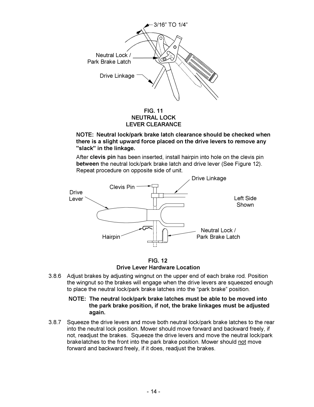
3/16” TO 1/4”
Neutral Lock /
Park Brake Latch
Drive Linkage ![]()
FIG. 11
NEUTRAL LOCK
LEVER CLEARANCE
NOTE: Neutral lock/park brake latch clearance should be checked when there is a slight upward force placed on the drive levers to remove any "slack" in the linkage.
After clevis pin has been inserted, install hairpin into hole on the clevis pin between the neutral lock/park brake latch and drive lever (See Figure 12). Repeat procedure on opposite side of unit.
| Drive Linkage |
Clevis Pin |
|
Drive | Left Side |
Lever | |
| Shown |
| Neutral Lock / |
Hairpin | Park Brake Latch |
FIG. 12
Drive Lever Hardware Location
3.8.6Adjust brakes by adjusting wingnut on the upper end of each brake rod. Position the wingnut so the brakes will engage when the drive levers are squeezed enough to place the neutral lock/park brake latches into the “park brake” position.
NOTE: The neutral lock/park brake latches must be able to be moved into the park brake position, if not, the brake linkages must be adjusted again.
3.8.7Squeeze the drive levers and move both neutral lock/park brake latches to the rear into the neutral lock position. Mower should move forward and backward freely, if not, readjust the brakes. Squeeze the drive levers and move the neutral lock/park brakelatches to the front into the park brake position. Mower should not move forward and backward freely, if it does, readjust the brakes.
- 14 -