
TR23KC specifications
The Exmark TR23KC is a stand-on mower that has gained attention in the landscaping industry for its superior performance and innovative features. Designed for both commercial and residential landscaping professionals, this model combines power, precision, and comfort in a versatile package that is ideal for a range of mowing applications.One of the standout features of the TR23KC is its robust engine. Powered by a reliable Kawasaki engine, the mower delivers exceptional cutting performance, making it suitable for tackling tough grass and uneven terrain. The engine ensures optimal fuel efficiency while providing enough power to handle demanding mowing tasks. This reliability allows landscapers to complete jobs quickly without sacrificing quality.
The cutting deck is another remarkable feature of the TR23KC. With a cutting width of 48 inches, it allows for efficient mowing over large areas. The deck is fabricated from high-quality materials, offering durability and resistance to wear and tear. The mower has adjustable cutting heights, enabling users to achieve the desired grass length, which is particularly beneficial for maintaining varying lawn conditions throughout the seasons.
In terms of comfort, the Exmark TR23KC includes an ergonomic stand-on platform. This design not only provides ease of use but also enhances operator visibility, offering an unobstructed view of the cutting area. The platform is equipped with anti-vibration features, reducing fatigue during long working hours, while the intuitive controls facilitate ease of use.
One notable technology integrated into the TR23KC is Exmark's innovative wheel technology. The large drive wheels enhance maneuverability and traction, allowing the operator to navigate around obstacles with utmost precision. The zero-turn capability further enhances its agility, making it simple to turn around tight corners and narrow spaces without needing to reposition.
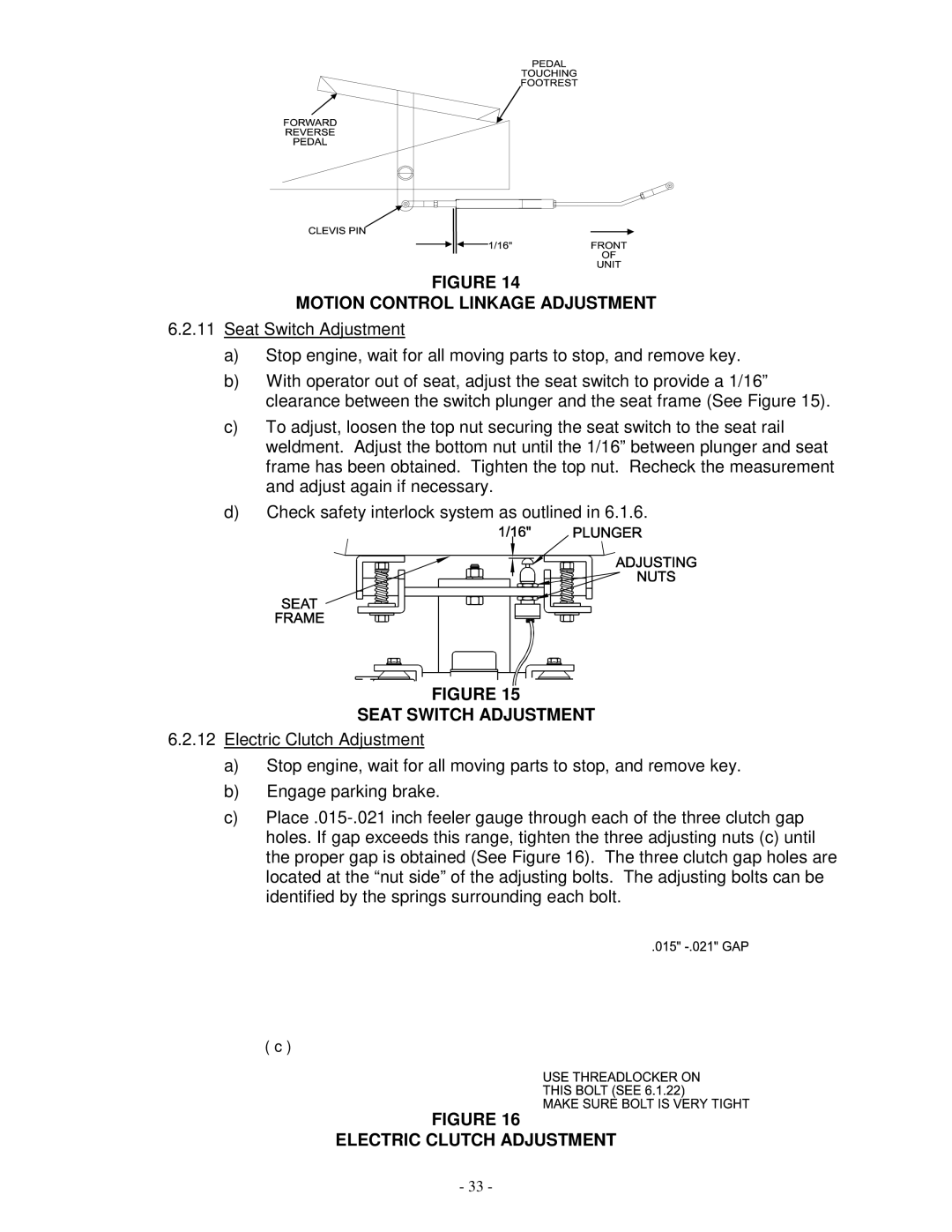
Safety is also prioritized in the design of the TR23KC. It features an automatic engine shut-off system that activates when the operator leaves the platform. This ensures that the mower remains safe to use and reduces the risk of accidents.
Overall, the Exmark TR23KC stand-on mower is an excellent choice for professionals seeking a machine that combines power, efficiency, and comfort. Its robust engine, durable cutting deck, ergonomic design, and advanced technologies make it a reliable option for tackling various mowing tasks, establishing it as a leader in the stand-on mower segment.