2.11 TORQUE REQUIREMENTS
BOLT LOCATION | TORQUE |
Blade/Cutter Housing Spindle Bolt | |
Caster Bracket Mounts | |
Cutter Deck/Engine Deck Mount | |
Engine Mounting Bolts (Kohler & Kawasaki) |
3.ASSEMBLY INSTRUCTIONS
3.1Uncrate unit, leaving it on the pallet, place upper handle assembly, fuel tank, and drive linkages at the rear of the machine. Place casters at the front of unit.
3.2Place a length of 4" x 4" block between the front of the cutter deck and the pallet.
3.3Remove the bolt bag from the top of the fuel tank support.
3.4Loosen the 5/16" hardware at the two (2) discharge deflector hinge points so that the deflector is snug, but can be moved up and down freely.
3.5Refer to Parts Manual to help you identify and locate parts and their proper position.
3.6Install casters to front of deck using appropriate hardware from the bolt bag (eight 3/8 x 3/4" bolts and eight 3/8" whizlock nuts); tightening the lower four bolts first, then the top four.
3.7Apply retaining adhesive
3.8Attach the fuel tank hose to the tank fitting and secure with the clamp provided. Make sure that fuel hose is not between engine and throttle plate on engine.
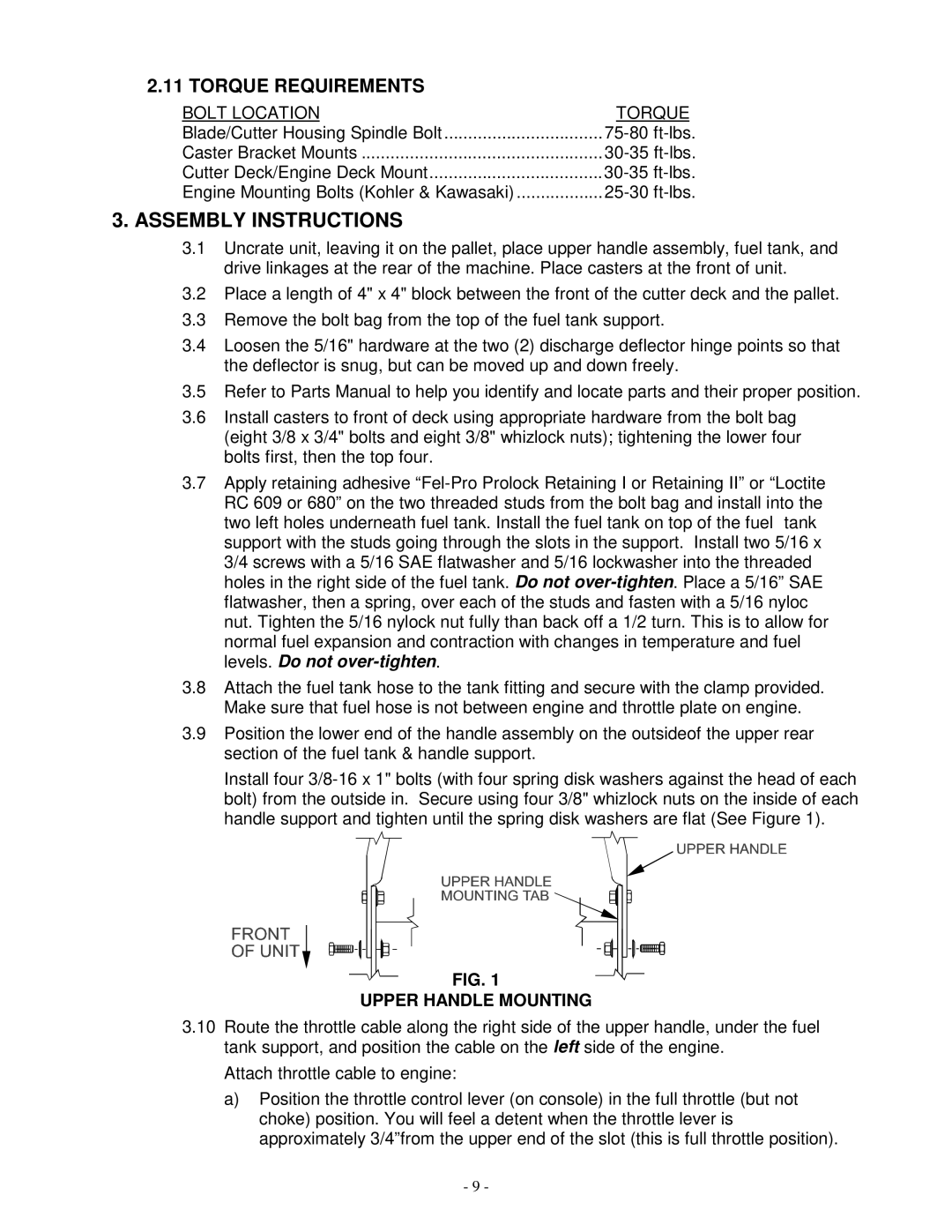
3.9Position the lower end of the handle assembly on the outsideof the upper rear section of the fuel tank & handle support.
Install four
FIG. 1
UPPER HANDLE MOUNTING
3.10Route the throttle cable along the right side of the upper handle, under the fuel tank support, and position the cable on the left side of the engine.
Attach throttle cable to engine:
a)Position the throttle control lever (on console) in the full throttle (but not choke) position. You will feel a detent when the throttle lever is approximately 3/4”from the upper end of the slot (this is full throttle position).
- 9 -