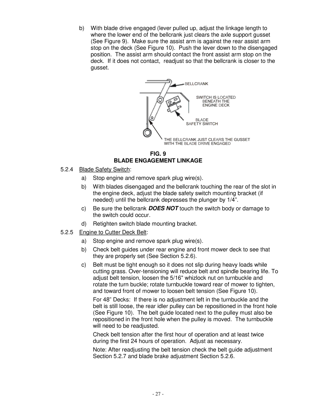
b)With blade drive engaged (lever pulled up, adjust the linkage length to where the lower end of the bellcrank just clears the axle support gusset (See Figure 9). Make sure the assist arm is against the rear assist arm stop on the deck (See Figure 10). Push the lever down to the disengaged position. The assist arm should contact the front assist arm stop on the deck. If it does not contact, readjust so that the bellcrank is closer to the gusset.
FIG. 9
BLADE ENGAGEMENT LINKAGE
5.2.4Blade Safety Switch:
a)Stop engine and remove spark plug wire(s).
b)With blades disengaged and the bellcrank touching the rear of the slot in the engine deck, adjust the blade safety switch mounting bracket (if needed) until the bellcrank depresses the plunger by 1/4”.
c)Be sure the bellcrank DOES NOT touch the switch body or damage to the switch could occur.
d)Retighten switch blade mounting bracket.
5.2.5Engine to Cutter Deck Belt:
a)Stop engine and remove spark plug wire(s).
b)Check belt guides under rear engine and front mower deck to see that they are properly set (See Section 5.2.6).
c)Belt must be tight enough so it does not slip during heavy loads while cutting grass.
For 48” Decks: If there is no adjustment left in the turnbuckle and the belt is still loose, the rear idler pulley can be repositioned in the front hole (See Figure 10). The belt guide located next to the pulley must also be repositioned in the front hole when the pulley is moved. The turnbuckle will need to be readjusted.
Check belt tension after the first hour of operation and at least twice during the first 24 hours of operation. Adjust as necessary.
Note: After readjusting the belt tension check the belt guide adjustment Section 5.2.7 and blade brake adjustment Section 5.2.6.
- 27 -
