e)To “prime” charge pump, loosen two hex socket head capscrews (shown in Figure 7)
f)If either drive wheel still does not rotate, stop and repeat steps (d) through (e) above for the respective pump. If wheels rotate slowly, the system may prime after additional running. Check oil level as stated in Section 5.1.8.
g)Allow unit to run several minutes after the charge pumps are “primed” with drive system in the full speed position. Check oil level as stated in Section 5.1.8.
h)Check hydro drive linkage adjustment as stated in Section 5.2.9.
5.1.11Check tire pressures. Service Interval: 40 hrs.
a)Stop engine and remove spark plug wire(s). Check air pressure in tires; recommended tire pressure is: rear, 12
b)Inflate tires to pressures stated above. Measure circumference of each drive tire. Adjust tire pressures within above range to try to make the circumferences match as closely as possible.
NOTE: Front caster tires have permanent tire sealant installed.
5.1.12Inspect Belt wear. Service Interval: 40 hrs.
a)Stop engine and remove spark plug wire(s).
b)Remove cutter deck belt shield to check mower primary and secondary (48” decks) belt condition.
c)Look under engine deck to check the pump drive belt condition.
d)Check all idler arms to be sure they pivot freely. Disassemble, clean and grease pivot bushings if necessary.
5.1.13Lubrication
Service Interval: Refer to Chart.
a)Stop engine and remove spark plug wire(s).
b)Lubricate fittings with one to two pumps of SAE No. 2
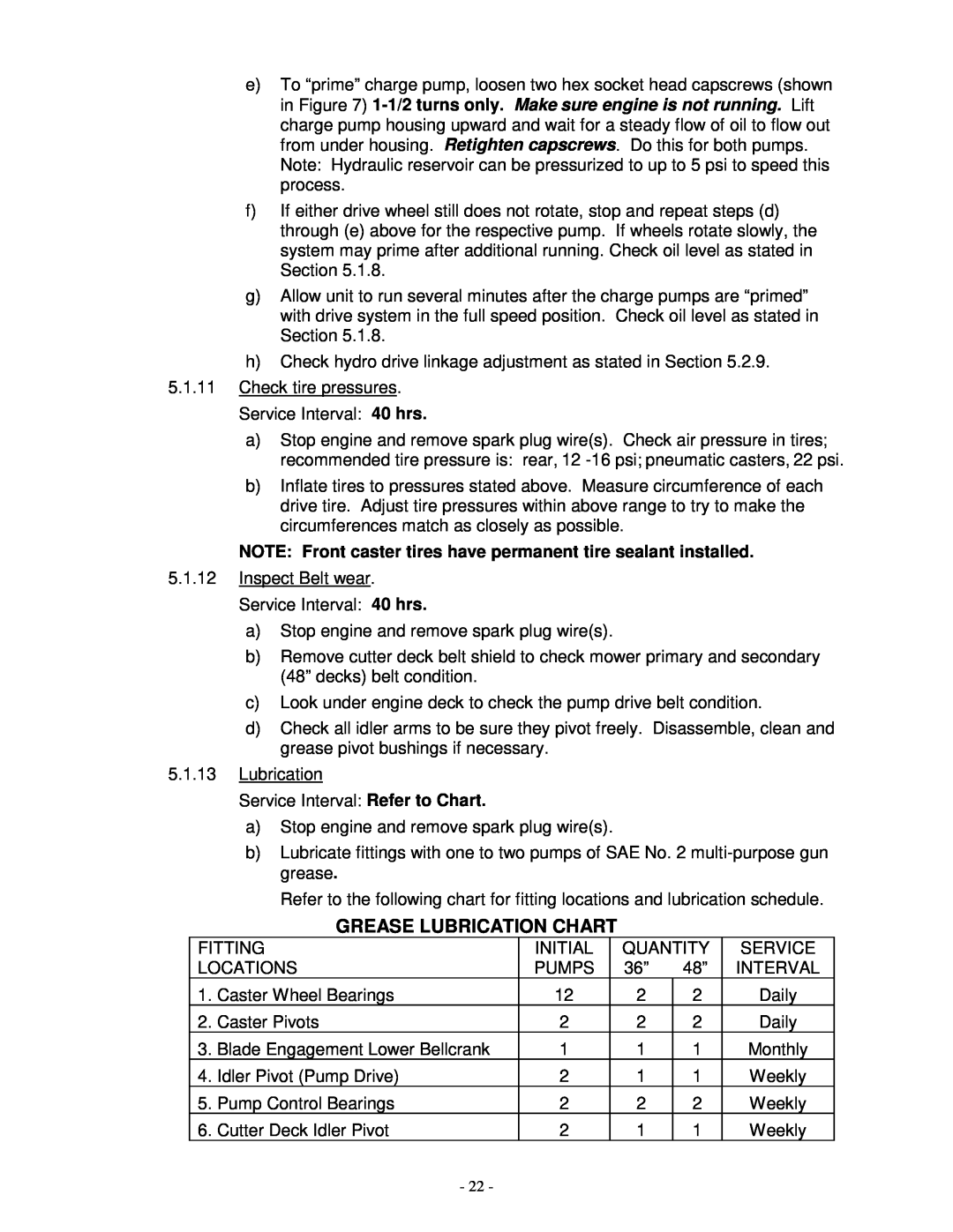
Refer to the following chart for fitting locations and lubrication schedule.
GREASE LUBRICATION CHART
FITTING | INITIAL | QUANTITY | SERVICE | ||
LOCATIONS | PUMPS | 36” | 48” | INTERVAL | |
1. | Caster Wheel Bearings | 12 | 2 | 2 | Daily |
2. | Caster Pivots | 2 | 2 | 2 | Daily |
3. | Blade Engagement Lower Bellcrank | 1 | 1 | 1 | Monthly |
4. | Idler Pivot (Pump Drive) | 2 | 1 | 1 | Weekly |
5. | Pump Control Bearings | 2 | 2 | 2 | Weekly |
6. | Cutter Deck Idler Pivot | 2 | 1 | 1 | Weekly |
- 22 -