Maintenance and Modifications
Removing and Installing an I/O Board or Blank Panel
W The FOX 4G Matrix 14400 fiber optic I/O boards |
output continuous invisible light, which may be |
harmful and dangerous to the eyes; use with caution. |
• Do not look into the rear panel fiber optic |
cable connectors or into the fiber optic cables |
themselves. |
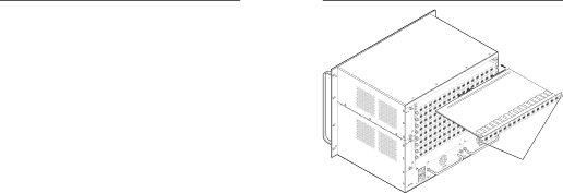
Align with
Plastic Guides
|
| P |
|
| O |
| N | P |
M |
| O |
L | N |
|
|
| |
K |
|
|
M |
|
|
• Plug the attached dust caps into the optical |
transceivers when the fiber optic cable is |
unplugged. |
N As factory configured, the fiber optic I/O boards are |
configured as either 100 percent singlemode or 100 percent |
multimode, but you can remove a fiber optic transceiver |
module (one input and one output) of one transmission |
mode and replace it with a block of the other transmission |
mode. |
You can mix transmission mode transceiver modules on |
J
|
|
| I |
|
|
| H |
|
|
| G |
|
|
| I |
|
|
| F |
|
|
| H |
|
| E | G |
|
|
| |
|
| D | F |
| B |
| |
|
| C |
|
|
| E |
|
|
| D |
|
A | B |
| |
|
| C |
|
|
| E |
|
|
| D | F |
A |
| ||
| B |
| |
|
| C |
|
|
| E | G |
|
| D | F |
|
|
| |
A | B | H | |
| I | ||
|
| C |
|
|
| E | G |
|
| D | F |
| A |
| |
B | H | ||
| I | ||
|
| C | J |
|
| E | |
|
|
| G |
|
| D | F |
| A |
| |
B | H | ||
|
| C |
|
|
| E | G |
|
|
| |
|
| D | F |
A | B |
| |
|
| C |
|
|
| E |
|
|
| D |
|
A | C |
| |
| SUPPLY | ||
|
| ||
| B | POWER | |
A | PRIMARY |
| |
|
|
|
P
O
N
M
L
K
J
I
H
G
F
E
D
C
B
A
Knurled
Knobs
a fiber optic I/O board, provided that you ensure that |
each fiber cable and connected devices are the appropriate |
transmission mode for the transceiver module. |
Typically, singlemode fiber has a yellow jacket and |
multimode cable has an orange jacket. |
NFor proper cooling and air flow, boards and/or blank panels should be installed in all locations during normal switcher operations.
NSee "A note on I/O boards", on page
Circuit boards can be replaced for fault correction. They also can be added or removed to increase or decrease the I/O configuration (size) of the switcher.
Remove and replace and I/O board or blank panel as follows:
NThe I/O boards are
1. For an I/O board, disconnect any connected cables.
2. Rotate the left and right knurled knobs to completely loosen the captive screws.
3. Gently pull on the knurled knobs/captive screws to loosen the board or panel from the backplane.
4. Slide the board or panel out of the chassis (next page).
4-2 FOX 4G Matrix 14400 • Maintenance and Modifications
CA
ANAHEIM,
CDo not touch the electronic components or the connectors on the backplane or on the circuit boards without being electrically grounded. Handle circuit boards by their edges only. Electrostatic discharge can damage circuits, even if you cannot feel, see, or hear it.
5. Place the removed board on an
6. For an I/O board, orient the board to be installed so that transceiver module A (fiber board) is on the left and transceiver module P is on the right.
7. For an I/O board, align the board with the left and right chassis guides (above).
8. Gently slide the board or blank panel into the enclosure. For an I/O board, slide the board toward the front panel until it meets resistance.
9. Gently seat the board or panel in the backplane.
10. Tighten the left and right knurled knobs/captive screws to lock the board or panel in place.
NIf necessary, use a screwdriver to tighten the knurled knobs/captive screws.
FOX 4G Matrix 14400 • Maintenance and Modifications |
Refer also to the FOX 4G Matrix 14400 User’s Manual at www.extron.com. | Refer also to the FOX 4G Matrix 14400 User’s Manual at www.extron.com. |
