Maintenance and Modifications, cont’d
Removing and Installing a Fan
The two fan modules are identical and
NThe fans modules are
1. Remove and retain the two screws that secure the row identification plate (identiying rows 1 through 80 or rows 81 through 144) to the fan. Retain the plate.
2. Rotate the top and bottom knurled knobs to completely loosen the captive screws.
3. Gently pull on the screws to loosen the fan from the backplane.
4. Slide the fan out of the chassis.
5. Orient the fan to be installed so that the printing on the back of the panel is
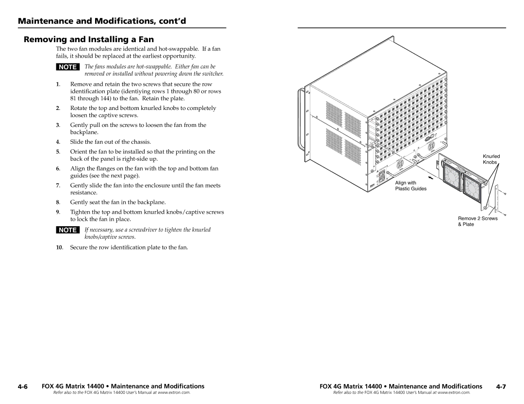
6. Align the flanges on the fan with the top and bottom fan guides (see the next page).
7. Gently slide the fan into the enclosure until the fan meets resistance.
8. Gently seat the fan in the backplane.
9. Tighten the top and bottom knurled knobs/captive screws to lock the fan in place.
NIf necessary, use a screwdriver to tighten the knurled knobs/captive screws.
10. Secure the row identification plate to the fan.
|
|
|
|
|
|
| P |
|
|
|
|
|
|
| O |
|
|
|
|
|
| N | P |
|
|
|
|
|
|
| |
|
|
|
| M |
|
| O |
|
|
|
| L |
| N |
|
|
|
|
|
|
|
| P |
|
|
|
| K |
|
|
|
|
|
|
| M |
|
| O |
|
|
|
| J |
|
|
|
|
|
|
| L |
| N |
|
|
|
| I | K |
|
| P |
|
|
| H | M |
|
| O |
|
|
|
| J |
|
|
|
|
|
| G | L |
| N |
|
|
|
| I | K |
|
| P |
|
|
| F | M |
|
| O |
|
|
| H | J |
|
| |
|
|
| E |
|
|
| |
|
|
| L |
|
|
| |
|
|
| G |
|
| N | P |
|
| D | I | K |
|
| |
|
|
| F |
|
|
| |
| C |
| H | M |
|
| O |
|
| E | J |
|
|
| |
|
|
| L |
| N |
| |
| B |
| G |
|
| P | |
| D | I | K |
|
| ||
|
| F |
|
|
| ||
| A |
| H |
|
|
| O |
| C |
| E | J |
|
|
|
|
|
| L |
|
|
| |
|
|
| G |
|
| N |
|
| B | D | I | K |
|
| P |
|
| F |
|
|
| ||
|
|
| M |
|
|
| |
| A |
| H | J |
|
| O |
| C |
| E |
|
|
| |
|
|
| L |
|
|
| |
|
|
| G |
|
| N |
|
| B | D | I | K |
|
| P |
|
| F |
|
|
| ||
| A |
| H |
|
|
| O |
| C |
| E | J |
|
|
|
|
|
| G | L |
| N |
|
| B | D | I |
|
|
| |
|
|
| F | K |
|
|
|
| A |
| H | M |
|
|
|
| C |
| E | J |
|
|
|
| B |
| G | L |
|
|
|
| D | I |
|
|
|
| |
|
|
| F | K |
|
| Y |
| A |
| H |
|
|
| SUPPL |
| C |
| E | J |
| POWER |
|
| B |
| G | REDUNDA | NT |
|
|
|
| F |
|
|
| ||
|
| D |
|
|
|
|
|
A |
| H |
|
|
|
| |
B |
|
|
|
|
|
| |
| C |
| E |
|
|
|
|
|
|
| G |
|
|
|
|
|
| D | F |
|
|
|
|
A |
|
|
|
|
| ||
B |
|
|
|
|
|
| |
| C |
| E |
|
|
|
|
|
|
|
|
|
|
| |
|
| D |
|
|
|
|
|
A |
| Y |
|
|
|
| |
C |
|
|
|
|
| ||
|
| SUPPL |
|
|
|
| |
B |
| Y POWER |
|
|
|
| |
A |
| PRIMAR |
|
|
|
| |
|
|
|
|
|
|
|
CA | Align with |
ANAHEIM, | Plastic Guides |
Knurled
Knobs
![]()
![]()
![]()
![]() 65-80
65-80
Remove 2 Screws & Plate
FOX 4G Matrix 14400 • Maintenance and Modifications | FOX 4G Matrix 14400 • Maintenance and Modifications |
Refer also to the FOX 4G Matrix 14400 User’s Manual at www.extron.com. | Refer also to the FOX 4G Matrix 14400 User’s Manual at www.extron.com. |