Installation and Operation, cont’d
6. If you are using a mounting bracket, follow the directions, if any, that came with the mounting bracket to attach the clips that fasten the bracket to the wall or furniture (figure
| Wall |
| Extron |
Push Mounting | IN9181 Wall |
Tabs Forward | Mounting Bracket |
2.If not already accomplished, attach the
3.Mount the CPM101 or other
Figure 2-5 shows a wall box installation. Mounting the mini-AAP panel to a mounting bracket is identical.
4.Power on all devices.
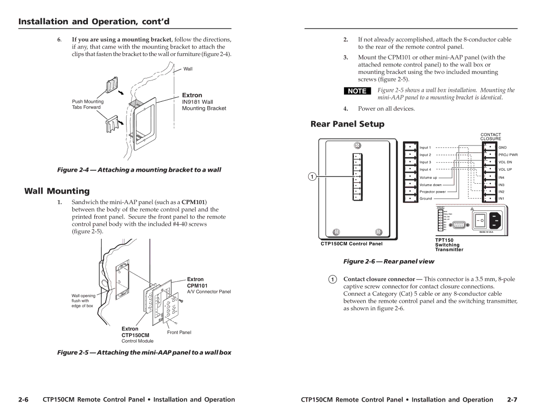
Rear Panel Setup
Figure 2-4 — Attaching a mounting bracket to a wall
Wall Mounting
1.Sandwich the
1
Input 1
Input 2
Input 3
Input 4
Volume up
Volume down
Projector power
Ground
CONTACT
CLOSURE
GND
PROJ PWR
VOL DN
VOL UP
IN4
IN3
IN2
IN1
CONTACT |
CLOSURE |
GND |
PROJ PWR |
VOL DN |
VOL UP |
IN4 |
IN3 |
IN2 |
IN1 |
MADE IN USA
CTP150CM Control Panel
TPT150
Switching
Transmitter
Extron
CPM101
A/V Connector Panel
Wall opening |
| OR |
flush with |
| PROJECT |
| POWER | |
PC |
| |
edge of box | 1 |
|
2 | VOLUP | |
| PC | UME |
|
| 1 |
| VIDEO | DOWN |
|
| |
|
| 2 |
| VIDEO |
|
Figure 2-6 — Rear panel view
1Contact closure connector — This connector is a 3.5 mm,
Extron CTP150CM
Front Panel
Control Module
Figure 2-5 — Attaching the mini-AAP panel to a wall box
CTP150CM Remote Control Panel • Installation and Operation | CTP150CM Remote Control Panel • Installation and Operation |