Instaltal lationandandOperation,cont’d
Installation Overview
CAUTION Installation and service must be performed by authorized personnel only. UL Listed electrical boxes are recommended. See UL Requirements for Wall Box Installation in this chapter.
1 | Power off all devices and disconnect them from the |
| power source, if necessary. |
2 | Run an |
UL Requirements for Wall Box Installation
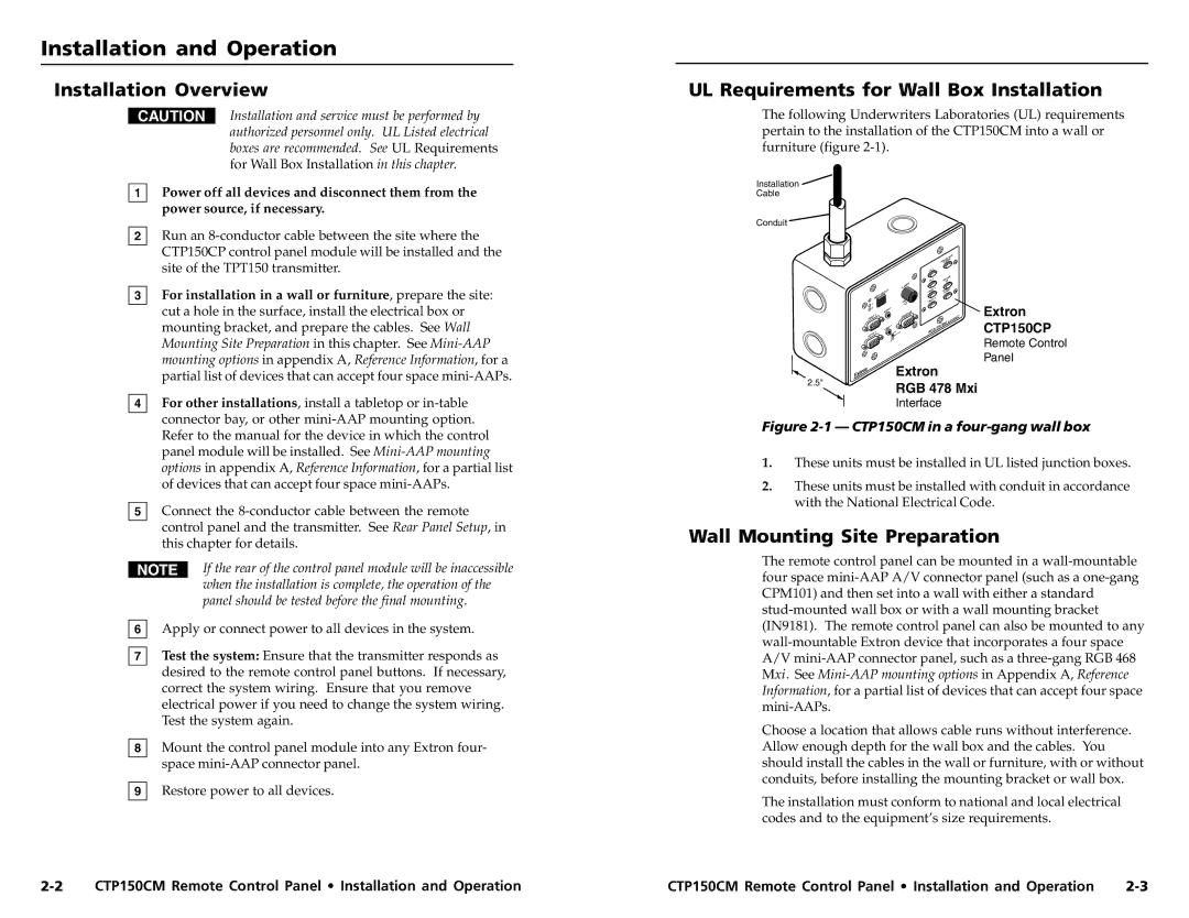
The following Underwriters Laboratories (UL) requirements pertain to the installation of the CTP150CM into a wall or furniture (figure
Installation
Cable
Conduit
CTP150CP control panel module will be installed and the |
site of the TPT150 transmitter. |
3 For installation in a wall or furniture, prepare the site: |
cut a hole in the surface, install the electrical box or |
mounting bracket, and prepare the cables. See Wall |
Mounting Site Preparation in this chapter. See |
mounting options in appendix A, Reference Information, for a |
partial list of devices that can accept four space |
4 For other installations, install a tabletop or |
connector bay, or other |
|
|
|
|
|
|
|
| TOR |
|
|
|
|
|
|
| JECR | |
|
|
|
|
|
|
| O | WE |
|
|
|
|
|
|
| PRPO | |
|
|
|
|
| PC | 1 |
|
|
|
|
|
|
|
|
|
| |
|
|
|
|
|
|
|
| E |
|
|
|
|
| PC | 2 |
| LUM |
|
|
|
|
|
| VOUP | ||
|
|
| H | . SHIFT |
|
|
| E |
|
|
|
| EO | 1 | LUM | ||
|
| SELECT |
|
| VID |
| DO | |
| INPUT |
|
| MIN/MAX | VID |
| 2 |
|
|
|
|
|
| EO |
|
| |
1 |
|
|
|
|
|
|
|
|
2 |
| DIO | 2 |
|
|
|
|
|
|
|
|
|
|
|
|
| |
|
| AU | MONITOR |
|
|
| ™ | |
| 2 |
|
|
|
| |||
INPUT |
|
|
|
|
|
|
| ADSP |
|
|
|
|
|
|
|
| WITH |
AU | 1 | Mxi |
DIO | 478 | |
1 |
| RGB |
INPUT |
|
|
2.5" | Extron | |
RGB 478 Mxi | ||
| ||
| Interface |
Extron CTP150CP
Remote Control Panel
Refer to the manual for the device in which the control |
panel module will be installed. See |
options in appendix A, Reference Information, for a partial list |
of devices that can accept four space |
5 Connect the |
control panel and the transmitter. See Rear Panel Setup, in |
this chapter for details. |
If the rear of the control panel module will be inaccessible when the installation is complete, the operation of the panel should be tested before the final mounting.
6Apply or connect power to all devices in the system.
7Test the system: Ensure that the transmitter responds as desired to the remote control panel buttons. If necessary, correct the system wiring. Ensure that you remove electrical power if you need to change the system wiring. Test the system again.
8Mount the control panel module into any Extron four- space
9Restore power to all devices.
Figure 2-1 — CTP150CM in a four-gang wall box
1.These units must be installed in UL listed junction boxes.
2.These units must be installed with conduit in accordance with the National Electrical Code.
Wall Mounting Site Preparation
The remote control panel can be mounted in a
Choose a location that allows cable runs without interference. Allow enough depth for the wall box and the cables. You should install the cables in the wall or furniture, with or without conduits, before installing the mounting bracket or wall box.
The installation must conform to national and local electrical codes and to the equipment’s size requirements.
CTP150CM Remote Control Panel • Installation and Operation | CTP150CM Remote Control Panel • Installation and Operation |