Hazardous Area Oxymitter DR
Instruction Manual
| 3.12 (79.25) MAX |
|
| |||||
| OUTLET CONNECTION |
|
| NOTE: DIMENSIONS ARE IN INCHES WITH | ||||
| 1 |
|
| 2.250 (57.15) |
| MILLIMETERS IN PARENTHESES. | ||
| 2 | OUTLET | 3 |
|
|
|
| |
|
|
|
|
|
|
| ||
|
|
|
|
|
|
|
| 2 |
4.81 | (122.17) |
|
|
|
| |||
|
|
|
|
|
| |||
|
|
|
|
| INLET CONNECTION | 8.50 | ||
|
|
|
|
|
|
|
| (215.90) |
FLOW SET |
|
|
|
|
|
|
| MAX |
POINT KNOB |
|
| 1.19 | 2.0 |
|
|
|
|
|
|
|
| 2 MOUNTING HOLES | ||||
|
|
| (30.22) |
| ||||
|
|
| (50.80) | |||||
|
|
|
| 3.19 | (81.03) | LG | ||
|
|
|
|
|
| |||
1.50THROUGH BODY FOR
| DRAIN VALVE |
|
|
|
|
|
|
|
| (38.10) | 0.312 (7.92) DIA BOLTS |
|
| |||||
|
|
|
|
|
|
|
|
|
|
|
|
| ||||||
|
| 10.0 |
|
|
|
|
|
|
|
|
|
|
|
|
|
|
| |
|
|
|
|
|
|
|
|
|
|
|
|
|
|
|
|
| ||
|
|
| (254) |
|
|
|
|
|
|
|
|
|
|
|
|
|
|
|
|
|
|
|
|
|
|
|
|
|
|
|
|
|
|
|
|
| |
0.250 OR 6 MM O.D. |
| REF |
|
|
|
|
|
| ||||||||||
|
|
|
|
|
|
| ||||||||||||
|
|
|
|
|
|
|
|
|
|
|
|
|
|
|
|
| ||
TUBE COMPRESSION |
|
|
|
|
|
|
|
|
|
|
|
|
|
|
|
|
| |
|
|
|
|
|
|
|
|
|
|
|
|
|
|
|
|
| ||
FITTING |
|
|
|
|
|
|
|
|
|
|
| 1 | FLOWMETER |
| 771B635H02 | |||
|
|
|
|
|
|
|
|
|
|
|
|
| 2 | 2" PRESSURE GAGE | ||||
|
|
|
|
|
|
|
|
|
|
|
|
|
|
|
|
| ||
|
| TO ELECTRONICS | 3 | COMBINATION | 4505C21G01 | |||||||||||||
|
|
|
|
|
|
|
| |||||||||||
OXYMITTER DR
SERIAL NO.
TAG NO.
0.250 OR 6 MM O.D. TUBING (SUPPLIED BY CUSTOMER)
REF AIR SET
263C152G01
INSTRUMENT AIR SUPPLY
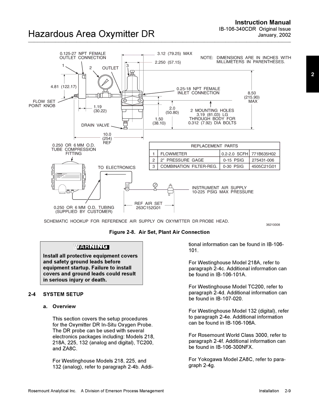
SCHEMATIC HOOKUP FOR REFERENCE AIR SUPPLY ON OXYMITTER DR PROBE HEAD.
36210008
Figure 2-8. Air Set, Plant Air Connection
Install all protective equipment covers and safety ground leads before equipment startup. Failure to install covers and ground leads could result in serious injury or death.
2-4 SYSTEM SETUP
a.Overview
This section covers the setup procedures for the Oxymitter DR
For Westinghouse Models 218, 225, and 132 (analog), refer to paragraph
tional information can be found in
For Westinghouse Model 218A, refer to paragraph
For Westinghouse Model TC200, refer to paragraph
For Westinghouse Model 132 (digital), refer to paragraph
For Rosemount World Class 3000, refer to paragraph
For Yokogawa Model ZA8C, refer to para- graph
Rosemount Analytical Inc. A Division of Emerson Process Management | Installation |