Instruction Manual
Hazardous Area Oxymitter DR
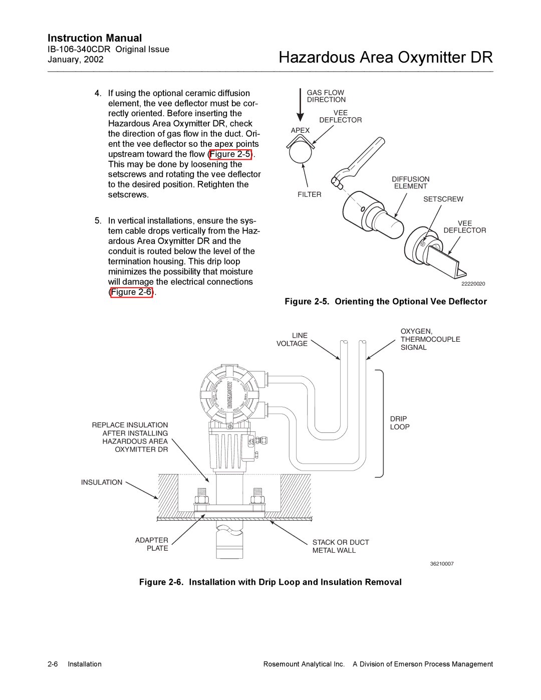
4.If using the optional ceramic diffusion element, the vee deflector must be cor- rectly oriented. Before inserting the Hazardous Area Oxymitter DR, check the direction of gas flow in the duct. Ori- ent the vee deflector so the apex points upstream toward the flow (Figure
5.In vertical installations, ensure the sys- tem cable drops vertically from the Haz- ardous Area Oxymitter DR and the conduit is routed below the level of the termination housing. This drip loop minimizes the possibility that moisture will damage the electrical connections (Figure
GAS FLOW
DIRECTION
VEE
DEFLECTOR
APEX
DIFFUSION
ELEMENT
FILTER
SETSCREW
VEE
DEFLECTOR
22220020
Figure 2-5. Orienting the Optional Vee Deflector
LINE | OXYGEN, | |
THERMOCOUPLE | ||
VOLTAGE | ||
SIGNAL | ||
|
REPLACE INSULATION AFTER INSTALLING HAZARDOUS AREA OXYMITTER DR
|
|
| E |
|
|
| R |
|
|
| E |
| S | P | H |
O | - |
| |
|
| ||
M |
|
| |
T | G |
| |
A | N |
|
|
I |
|
| |
N |
|
| |
E R |
| ||
V |
|
|
|
I A |
| ||
SW | |||
O |
|
| |
L- | |||
P | |||
| X | ||
|
|
| E |
|
|
| N I |
-
-
EVI |
|
LA |
|
T |
|
I |
|
U | |
| C |
| R |
| I |
| C |
| N |
| E |
| H |
| W |
IG | T |
| |
| |
T |
|
EP |
|
KE |
|
DRIP
LOOP
GAS
CAL.
INSULATION
ADAPTER | STACK OR DUCT |
PLATE | METAL WALL |
|
36210007
Figure 2-6. Installation with Drip Loop and Insulation Removal
Rosemount Analytical Inc. A Division of Emerson Process Management |