Hazardous Area Oxymitter DR
Instruction Manual
c.WESTINGHOUSE MODEL 218A ELEC- TRONICS SETUP
Before beginning operation, it is important that the probe heater setpoint of the existing electronics be changed to support the Haz- ardous Area Oxymitter DR probe. To con- vert the Model 218A Digital Electronics Package for use with the DR probe, an EPROM change is necessary. Remove Main PCB and check back of board to iden- tify unit as G02 or G04. The replacement EPROM needed is as identified below:
| G02 | G04 |
United States | 1M03192G01 | 1M02982G01 |
United Kingdom | 1M03192G02 | 1M02982G02 |
Germany | 1M03192G03 | 1M02982G03 |
France | 1M03192G04 | 1M02982G04 |
Italy | 1M03192G05 | 1M02982G05 |
NOTE
The replacement EPROM when using a multiprobe averager unit is
1M02982G10.2
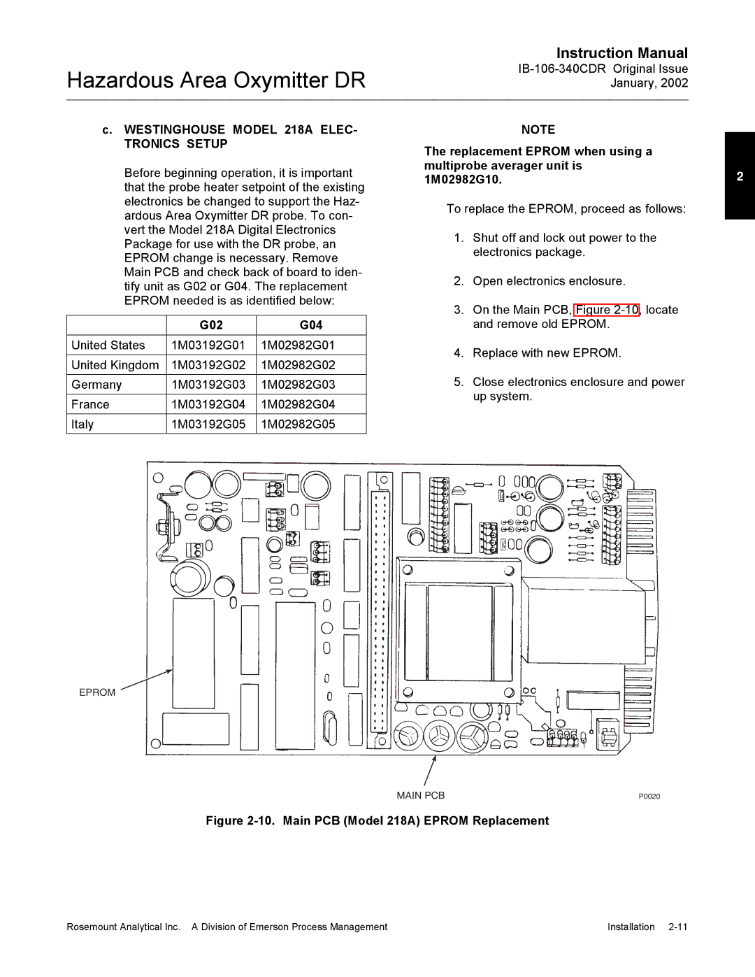
To replace the EPROM, proceed as follows:
1.Shut off and lock out power to the electronics package.
2.Open electronics enclosure.
3.On the Main PCB, Figure
4.Replace with new EPROM.
5.Close electronics enclosure and power up system.
EPROM
MAIN PCB | P0020 |
Figure 2-10. Main PCB (Model 218A) EPROM Replacement
Rosemount Analytical Inc. A Division of Emerson Process Management | Installation |