Instruction Manual
Appendix A
January, 2002
Hazardous Area Oxymitter DR
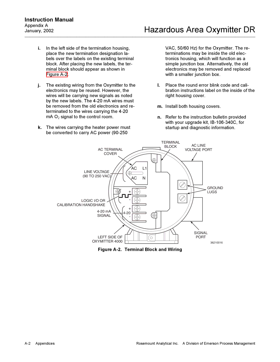
i.In the left side of the termination housing, place the new termination designation la- bels over the labels on the existing terminal block. After placing the new labels, the ter- minal block should appear as shown in Figure
j.The existing wiring from the Oxymitter to the electronics may be reused. However, the wires will be carrying new signals as noted by the new labels. The
k.The wires carrying the heater power must be converted to carry AC power
AC TERMINAL
COVER
VAC, 50/60 Hz) for the Oxymitter. The re- terminations may be inside the old elec- tronics housing, which will function as a simple junction box. Alternatively, the old electronics may be removed and replaced with a smaller junction box.
l.Place the round error blink code and cali- bration instructions label on the inside of the right housing cover.
m.Install both housing covers.
n.Refer to the instruction bulletin provided with your upgrade kit,
TERMINAL
BLOCK AC LINE
VOLTAGE PORT
LINE VOLTAGE | AC | L1 |
|
| |
(90 TO 250 VAC) | AC | N |
| ||
| + | GROUND |
| LUGS | |
LOGIC I/O OR | - |
|
CALIBRATION HANDSHAKE | + |
|
| ||
| ||
SIGNAL |
| |
- |
| |
|
| SIGNAL |
LEFT SIDE OF |
| PORT |
OXYMITTER 4000 |
| 36210016 |
Figure A-2. Terminal Block and Wiring
Rosemount Analytical Inc. A Division of Emerson Process Management |