Hazardous Area Oxymitter DR
Instruction Manual
Appendix A
January, 2002
A
APPENDIX A
UPGRADING HAZARDOUS AREA OXYMITTER DR TO
FULL HAZARDOUS AREA OXYMITTER
A-1 UPGRADE PROCEDURE
Perform the following procedure to upgrade the Hazardous Area Oxymitter DR to a full Hazard- ous Area Oxymitter.
a. Remove power from the Oxymitter DR. |
|
b. Remove the left and right covers from the |
|
Oxymitter termination housing. |
|
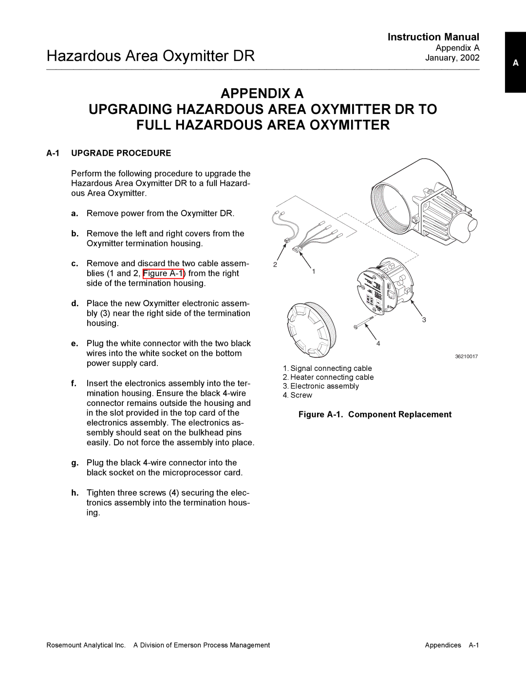
c. Remove and discard the two cable assem- | 2 |
blies (1 and 2, Figure | 1 |
side of the termination housing. |
|
d.Place the new Oxymitter electronic assem- bly (3) near the right side of the termination housing.
D |
|
|
|
|
|
| |
| IAG |
|
|
|
|
|
|
C | ANOSTIC |
| TER |
|
| ||
LARMS |
|
|
| ||||
| ALIBRAT |
| C | HEA | T |
|
|
|
| 02 |
|
| |||
|
| ION |
| HEA T/C |
| ||
|
|
|
| ER |
| ||
|
|
|
| ALIBRACELLT |
| ||
| OINTS RECOMMENDED2 |
| |||||
| P T |
|
|
| ION |
| |
| EST |
| 0 |
|
|
| |
| I |
|
| 02CELL | mv |
| |
|
|
| HEACELLT |
| |||
|
|
|
| H |
| mV + | |
| NC |
|
| EATER T | - | ||
| H | I |
|
| ER | /C | + |
| GIGH | NC |
|
|
| T/C | - |
| AS | LOW |
|
|
|
|
|
| D | GAS |
| CAL |
|
| |
| EC | DEC |
|
|
| ||
|
|
| T |
|
|
| |
|
|
|
|
|
|
| |
|
|
|
| EST |
|
| |
|
|
|
| PR | O GAS | + | |
|
|
|
|
| CESS | - | |
|
|
|
|
| % 02 | ||
3
e.Plug the white connector with the two black wires into the white socket on the bottom power supply card.
f.Insert the electronics assembly into the ter- mination housing. Ensure the black
g.Plug the black
h.Tighten three screws (4) securing the elec- tronics assembly into the termination hous- ing.
4
36210017
1.Signal connecting cable
2.Heater connecting cable
3.Electronic assembly
4.Screw
Figure A-1. Component Replacement
Rosemount Analytical Inc. A Division of Emerson Process Management | Appendices |