DSC 301 HD specifications
The Extron DSC 301 HD is a powerful digital scaler designed for high-definition video applications, making it an essential tool for professional AV installations. This device is particularly well-suited for those working in multichannel environments, requiring seamless video processing for presentations, broadcasting, and various multimedia displays.One of the standout features of the DSC 301 HD is its ability to scale video input signals across a wide range of resolutions. It supports resolutions up to 1080p and even 2K, ensuring compatibility with the latest high-definition content and display technologies. This flexibility allows users to easily integrate diverse sources, such as computers, Blu-ray players, and other HDMI signal sources, into their AV setups without compromising on quality.
The DSC 301 HD employs Extron's proprietary Image Perfect scaling technology, which ensures that aspect ratios, sharpness, and color fidelity are maintained during the scaling process. This feature is crucial for maintaining the integrity of images, particularly when dealing with variable resolutions. Users can expect pristine video output whether the input is from a PC or a video camera, ensuring a consistent viewing experience.
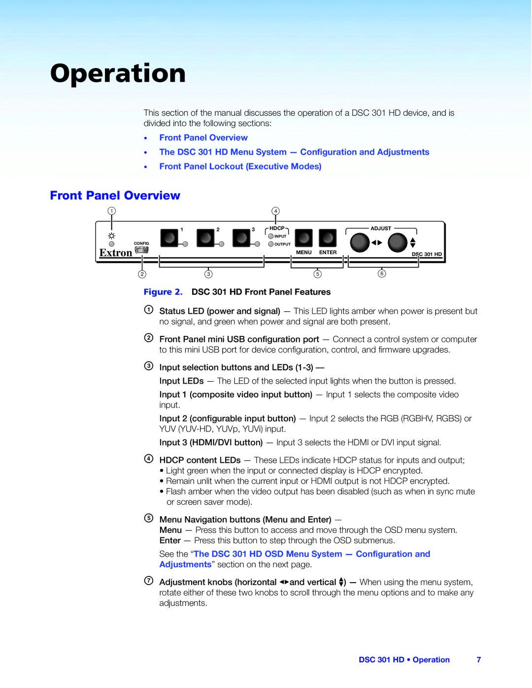
In terms of connectivity, the DSC 301 HD is equipped with various input and output options, including HDMI, VGA, and composite video connectors. This ensures that it can accommodate a wide range of devices and output to different types of displays, allowing for versatile AV configurations. Additionally, the device supports audio embedding and de-embedding, making it suitable for integrated sound systems.
The DSC 301 HD also includes advanced features such as input signal detection, which automatically switches inputs based on the presence of a signal, and comprehensive EDID management, ensuring optimal communication between connected devices for resolution and configuration. Furthermore, the built-in test patterns assist in troubleshooting and installation, which can greatly enhance user experience and reduce setup time.
With a user-friendly interface, the Extron DSC 301 HD provides accessible control options, including front panel buttons and remote control capabilities. It integrates seamlessly with Extron's Global Configurator software, allowing for customizable configuration and management, making it an ideal choice for complex AV installations and environments requiring high functionality and reliability.
In summary, the Extron DSC 301 HD stands out as a robust solution for high-definition scaling needs, combining advanced technologies, extensive connectivity options, and user-friendly features, making it an excellent investment for professional AV users.

