Manuals
/
Extron electronic
/
Home Audio
/
Satellite Radio
Extron electronic
DTP HDMI 301
manual
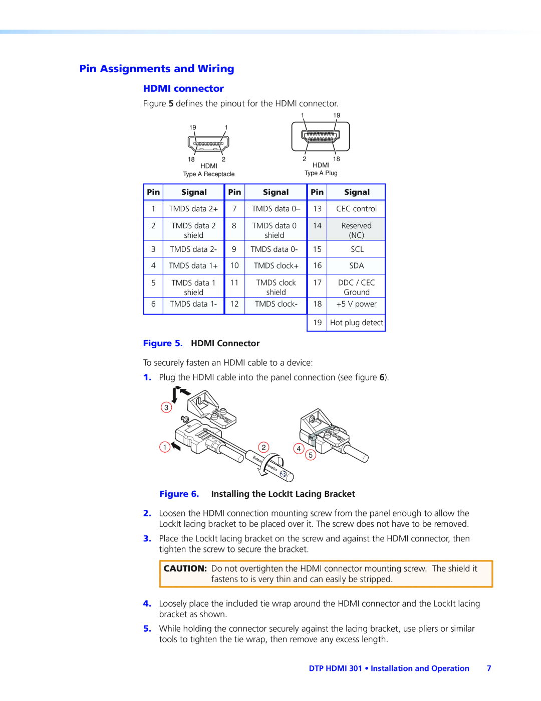
Pin Assignments and Wiring, HDMI connector
Models:
DTP HDMI 301
1
13
23
23
Download
23 pages
395 b
10
11
12
13
14
15
16
17
Specs
Install
Pin Assignments and Wiring
Warranty
Part Numbers and Accessories
RS-232and IR connector wiring
Safety
Power supply wiring
Features
Page 13
Image 13
Page 12
Page 14
Page 13
Image 13
Page 12
Page 14
Contents
User Guide
DTP HDMI
DVI & HDMI Extenders
HDMI Twisted Pair Extender
Consignes de Sécurité Français
Safety Instructions English
Sicherheitsanleitungen Deutsch
Instrucciones de seguridad Español
FCC Class A Notice
Copyright
Conventions Used in this Guide
Trademarks
Installation and Operation
Contents
Introduction
Reference Information
DTP HDMI 301 Contents
Introduction
Features
About this Guide
About this Guide
TP Cable Advantages
Features
Control Communications
Mounting the Transmitter or Receiver
Installation and Operation
Connections
Transmitter Connections
that is embedded in the HDMI input
Receiver Connections
wires may touch, causing a short circuit
HDMI connector
Pin Assignments and Wiring
Figure 7. TP Cable Termination
TP cable termination
Terminating shielded cable
Figure 10. Crimped RJ-45Connector
Figure 8. Peeling Back the Cable Shielding
Figure 9. Wrapping the Shielded Tape
Figure 11. Power Connector Wiring
Power supply wiring
Operation
RS-232and IR connector wiring
Specifications Part Numbers and Accessories
Specifications
Reference Information
Video
Audio output
Audio input
DTP HDMI 301 Reference Information
DTP HDMI 301 Reference Information
General
Transmitter/Receiver Pair Part Numbers
Part Numbers and Accessories
Included Parts
Cables and Adapters
Tabletop Use
Mounting Accessories
Mounting kits
UL Rack-MountingGuidelines
Extron Warranty
Top
Page
Image
Contents