Hardware Setup
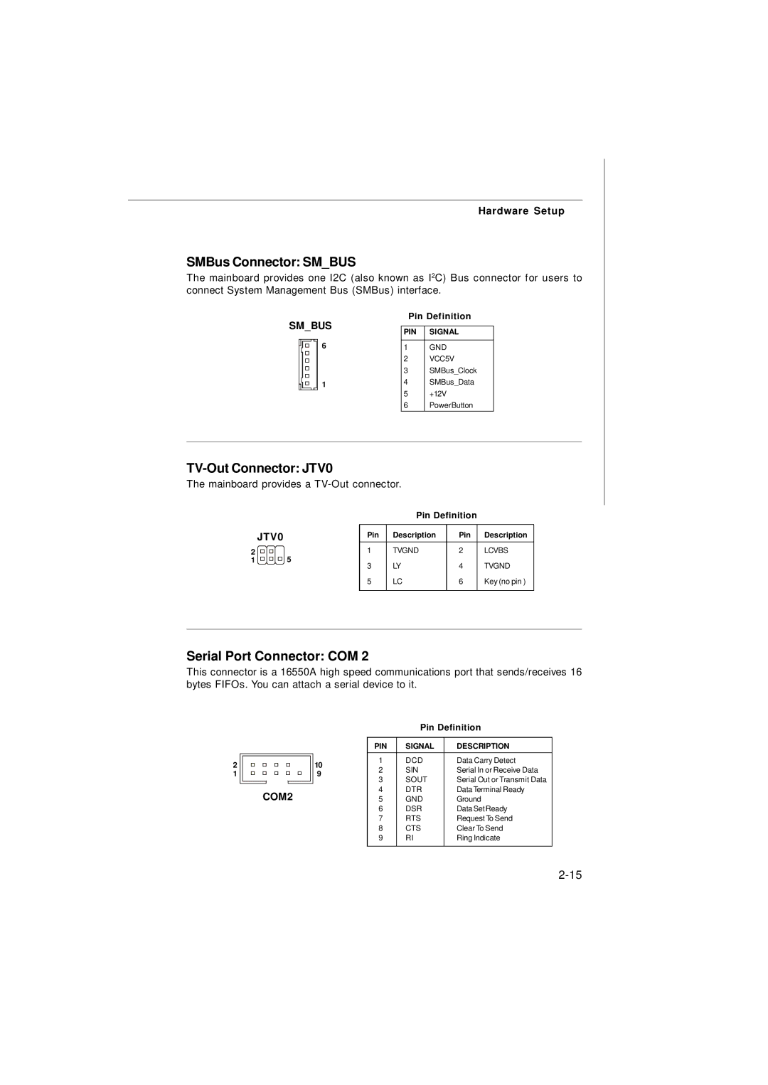
SMBus Connector: SM_BUS
The mainboard provides one I2C (also known as I2C) Bus connector for users to connect System Management Bus (SMBus) interface.
Pin Definition
SM_BUS | PIN | SIGNAL | ||
|
|
| ||
|
|
| 1 | GND |
|
| 6 | ||
|
|
| 2 | VCC5V |
|
|
| 3 | SMBus_Clock |
|
| 1 | 4 | SMBus_Data |
|
|
| 5 | +12V |
|
|
| 6 | PowerButton |
TV-Out Connector: JTV0
The mainboard provides a
|
| Pin Definition |
| |
JTV0 | Pin | Description | Pin | Description |
2 | 1 | TVGND | 2 | LCVBS |
1 | 5 | LY | 4 | TVGND |
| 3 | |||
| 5 | LC | 6 | Key (no pin ) |
Serial Port Connector: COM 2
This connector is a 16550A high speed communications port that sends/receives 16 bytes FIFOs. You can attach a serial device to it.
2
1
|
|
|
|
| Pin Definition | |
|
|
|
| PIN | SIGNAL | DESCRIPTION |
|
|
| 10 | 1 | DCD | Data Carry Detect |
|
|
| ||||
|
|
| 2 | SIN | Serial In or Receive Data | |
|
|
| 9 | |||
|
|
| 3 | SOUT | Serial Out or Transmit Data | |
|
|
|
| |||
|
|
|
| |||
COM2 |
| 4 | DTR | Data Terminal Ready | ||
| 5 | GND | Ground | |||
|
|
|
| 6 | DSR | Data SetReady |
|
|
|
| 7 | RTS | Request To Send |
|
|
|
| 8 | CTS | Clear To Send |
|
|
|
| 9 | RI | Ring Indicate |